Dear Daan,
I am sure this distinction is of great importance to you. However, most of us are just grateful that HD (high distortion?) freely published another design, and X makes it avaible, based on an expert PCB design. This is my first SS amp to be built and listened to in over 20 years. I am looking forward to very much.
Yes Francois obviously I am a nitpicker 😉.
It is (still) my feeling that there is a false claim.
For the rest, I fully agree that it is great to see new designs, and that there are people making it available for DIY.
Be aware that it has never been (and is) my aim to disqualify.
Last edited:
My only aim is that (still) my feeling is that there is a false claim.
Which one? I have a hard time following your changing opinions.
Class A -- not class A -- class A again ?
Not SE -- SE -- not SE again ?
No offense meant but it is getting really difficult to believe anything you say.
Yes my opinions changed because I don't have Nelson Pass / John Broskie level to judge circuits.
That's why I asked for comments at for example the Blowtorch thread.
Only Bonsai took the effort to react there; the other socalled super duper EE's like Curl, Wurcer and others don't react because apparently it is "below their standing", or simply because they are too busy in their own limited world.
A very clever and qualified person however, backed up by an accurate sim, told me that the Nirvana amp has a class A output stage working in push pull (post #386).
Other qualified members here, Kokoriantz (post #14) and Bigun, also see the output stage as being push pull.
Even Hugh (post #19) mentions the design SEPP, which means push pull output stage.
I hope to be clear enough.
Last edited:
Gentlemen, is NFB not the same as DFB?
JP
No, DFB is "Deutscher Fußball Bund" 😀😀
So is it a SEPP or SRPP? Either way it's just a label and you don't judge the way an amplifier sounds based on it's name.
Has anyone done a comparison of the new Alpha Nirvana to the Alpha20?
Has anyone done a comparison of the new Alpha Nirvana to the Alpha20?
So is it a SEPP or SRPP?
Topology-wise SEPP is ~ SRPP.
Read all about it here:
The Tube CAD Journal,SRPP Decoded
Either way it's just a label and you don't judge the way an amplifier sounds based on it's name.
Agree.
i put little faith in simulations, do the actual ftc testing, using a real dummy load, a scope, distortion meters to show your results of the real amp in real time, not simulations....
to me simulations are not a proof of anything, the built up amp will show real time results....
without real time testing and results, everything is just opinions...
folks deserve to know the truth.....
to me simulations are not a proof of anything, the built up amp will show real time results....
without real time testing and results, everything is just opinions...
folks deserve to know the truth.....
folks deserve to know the truth.....
At least that is true......
...With active components the maximum efficiency in class A is 25%; with inductive load the maximum is 50%......
No. At best incompletely stated.
In terms of Power Transfer we have the four forms in the attachment. "25%" is the un-traditional form with a CCS (not a true current source) DC feed. While it has been around here and there forever, I first saw it in a Dan Mayer headphone amp. It took me a while to see why it is "rarely" used for loudspeakers. (And when fashion and opinion edged good circuit design, it did appear in several loudspeaker amps.)
I never know what "single ended" is supposed to mean. One hand clapping? ALL audio amps are "push-pull", though we tend to reserve that term for two active elements, don't count resistors or coils as the "pull" they are. Sometimes just "no transformer". In today's audio-world it may mean "has some sonic aspect of one hand clapping". This Nirvana could be seen as single ended at every stage. However the last two "SE" stages form an Ouroboros ring. Clever. SE? PP? Too deep for me.
Attachments
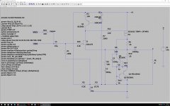
Finally a picture of his sim, clearly demonstrating the OPS to be push pull.
Is this SE or PP?
What happens if we omit Q4 and associated components completely?
Ignore the performance, I know it's very poor but the circuit has moved on since I did this.
Attachments
If we remove Q4, then:
1. At pos half cycle, upper device controls voltage AND current into the load, and
2. At neg half cycle, lower device(s) controls voltage AND current into load.
In this sense, two devices are constrained to their respective half cycle and both voltage and current, this is PUSH PULL. If set up in AB or B, inactive devices will turn off completely. In Class A, inactive devices will never turn off. Devices turning off is a significant issue for creating harmonic artefacts and regarded as essential to be defined as a Class A amplifier.
With Q4 in place (that is, set up as an active current flip-flop across the two output device currents), then:
3. At pos half cycle, upper device controls voltage AND current into the load, and
4. At neg half cycle, upper device controls voltage BUT NOT current into the load, this load current is directed by the lower device alone, which never turns off and never controls voltage (signal).
From this odd combination of different control of the signal with two outputs, we can see that the upper device is the sole device controlling voltage through the entire waveform. This MUST happens only if all devices DO NOT TURN OFF. The upper 'voltage defining' device does not control current in the negative half cycle, however; this is passed to the lower device, but this lower device does NOT turn off. Neither does the lower device EVER control voltage at the load at any point of the waveform.
Because the total control of the voltage at the load is devolved to the upper device, in this sense this is regarded as single ended control, as though only one device were controlling the entire waveform. This is almost a semantic difference, but it is significance, because at the entire negative half cycle, the lower device controls load current. It is true this control is tightly controlled by the constant on upper device which forces voltage control at all times, but it can be viewed as Single Ended.
The correct term, however, attributes more correct reality with the phrase, SINGLE ENDED PUSH PULL.
This is very interesting mind puzzle because with very simple circuits we can run into serious difficulties describing precisely what is happening, particularly were we are using terms from the past which are morphing into the future.
HD
Last edited:
My bad - I should have been clearer that the removal of Q4 would result in no standing current at all. Some more components have to be added to make the amplifier operate.
As the CCS (the lower half of the circuit) is moved from fully fixed (by replacing Q4 and the R9-R10 tail with Vref and appropriate current control resistor) to fully variable, the operation of the circuit changes from a pure SE to a pure push pull - even if the lower transistor is not driven directly by the input/VAS stage.
Therefore it's a SE amp, operated in PP. Sometimes both answers are correct.
there is nothing new in Nirvana . I have posted 2years ago Another JLH, my 2SJLH PMOSFET DC Class-A amp a headphone amp that I certainly copied from this website. It is simply SRPP.Yes my opinions changed because I don't have Nelson Pass / John Broskie level to judge circuits.
That's why I asked for comments at for example the Blowtorch thread.
Only Bonsai took the effort to react there; the other socalled super duper EE's like Curl, Wurcer and others don't react because apparently it is "below their standing", or simply because they are too busy in their own limited world.
A very clever and qualified person however, backed up by an accurate sim, told me that the Nirvana amp has a class A output stage working in push pull (post #386).
Other qualified members here, Kokoriantz (post #14) and Bigun, also see the output stage as being push pull.
Even Hugh (post #19) mentions the design SEPP, which means push pull output stage.
I hope to be clear enough.
Attachments

KK,
That is the TimS simple headphone amp, which I have built and tested. It sounds very nice but I don’t think the topology is quite the same.
Simple High Performing Headphone Amp
Here was my home etched version:
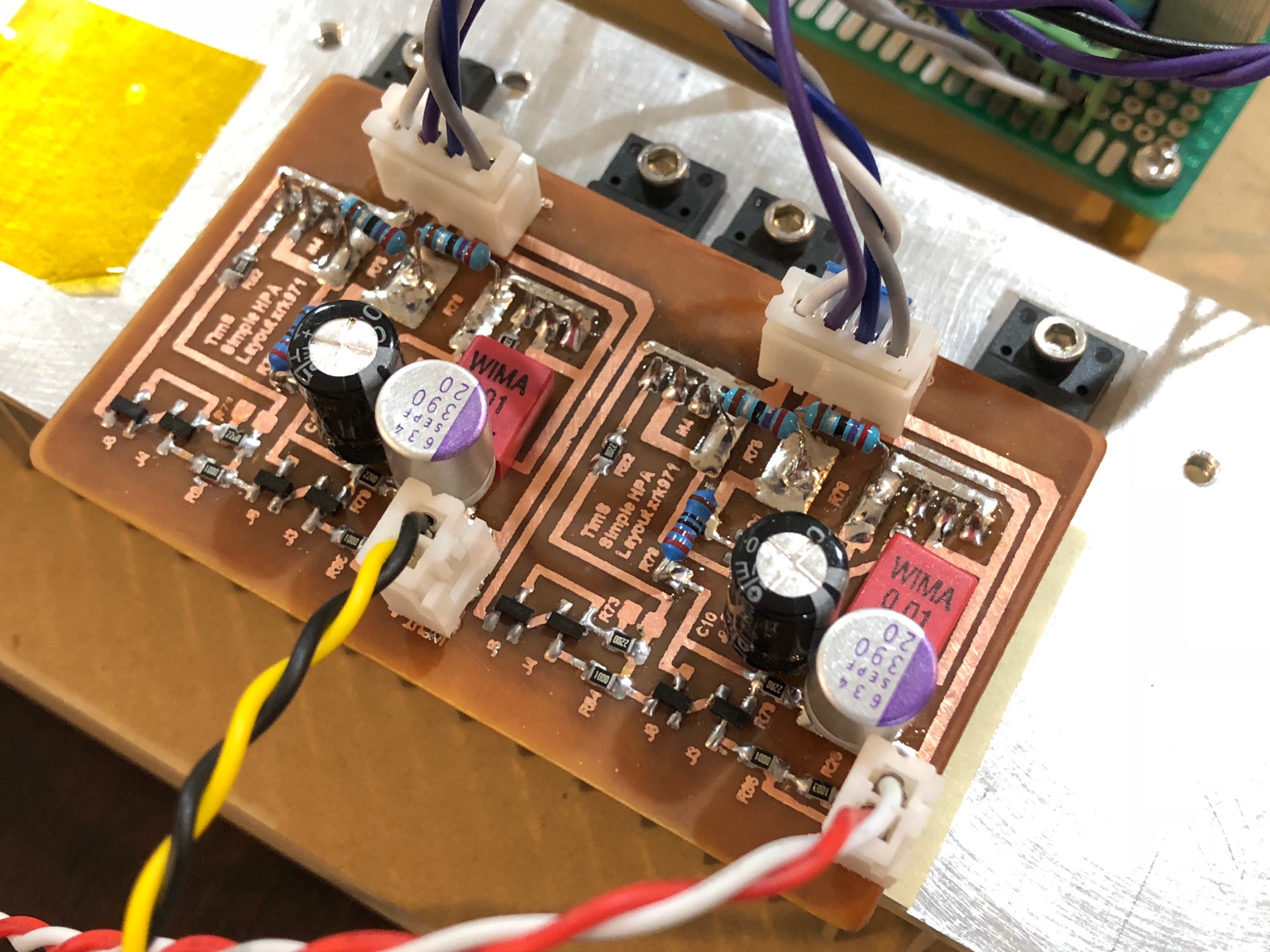
If you look carefully, both outputs are P channels, and the input stage is not an Aksa Lender-LNP (long neck pair BJT) but JFETs with a CCS.
It is SEPP though.
That is the TimS simple headphone amp, which I have built and tested. It sounds very nice but I don’t think the topology is quite the same.
Simple High Performing Headphone Amp
Here was my home etched version:
If you look carefully, both outputs are P channels, and the input stage is not an Aksa Lender-LNP (long neck pair BJT) but JFETs with a CCS.
It is SEPP though.
haha no....I am waiting for the technical report to debug the 39W class A "misunderstanding"...
Correct me if I'm wrong, but the top NMOS in the ALPHA/Alpha Nirvana with associated connections basically acts as a gyrator, ie: Gyrator circuit: simulate large coils electronically
The extremely low RDS_On of these power MOSFETS allows the parasitic resistance to reach extremely low levels and therefore the circuit approaches an ideal inductor with the meaningful resistance loss only being 0.22 + ~RDS_On ohms.
From this, if I'm correct in my general analysis, we can conclude that the circuit is, indeed, Class-A and the efficiency can approach 50% because of the large (tens of H) inductive current source and very low series resistance.
Last edited:
- Home
- Amplifiers
- Solid State
- Discussion of Alpha Nirvana Operation