...with inductive load the maximum is 50%...
Is not the active load accomplishing much the same as a choke load? SS tends to mystify me, but when i was studying parafeed tue amps a choke or CCS could be used.
dave
Dave,
Yes it does.
But a choke is a passive component with very little power dissipation; an active current source/sink dissipates at least the same amount of power as the output device, be it a transistor or a tube.
Yes it does.
But a choke is a passive component with very little power dissipation; an active current source/sink dissipates at least the same amount of power as the output device, be it a transistor or a tube.
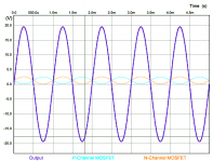
I don't see much more than 3.4A pk-pk for Nirvana amp; maybe a bit more with bootstrapping, but 6A pk-pk??
As I explained earlier, the two output transistors each flow 3A but out of phase and in opposition to generate a net 6amp at the load.
Look at the plots of the currents in R12 and R13 (3A ea and 180 deg out of phase), then look at current vs time in load resistor RL1. It is 6A peak to peak.
Currents in R12/13:
The difference in currents at summing junction (output node) results in current through RL1 of 6A:
Schematic:
Look at the topology of the reactive CCS around Q4 and the PMOS. It permits the bottom output to generate a current of same amplitude but 180deg out of phase. The two outputs indeed dissipate the same power. Usual rail voltage x 2 x bias current or 47w ea x 2 = 94w.
Last edited:
are you going to disable your account too daanve? that would be very wise
haha no....I am waiting for the technical report to debug the 39W class A "misunderstanding"...
Oh no, not this ‘it ain’t really Class A’ argument again?
Well you might stop....
BTW, one question to the experts, only as a curiosity. If feedback increases, would the harmonics be even smaller? I guess it is below 29 dB like Hugh and you like, how much GNFB?
diyaudio Alpha Nirvana 39w 8ohm Class A Amp feedback NFB - Google Search
nothing.
diyaudio Alpha Nirvana 39w 8ohm Class A Amp feedback NFB - Google Search
nothing.
Last edited:
Maty,
When the global fb is increased, the amplitude of the higher orders drops very little but their number increases, as we correct the corrections....... at low global fb, the low order amplitudes are higher, but there are much less higher orders.
X has given fantastic numbers for the AN, this is VERY low for any amp, tube or SS.
Generally, lower gfb gives you higher THD however, and this is not acceptable to many designers.
Thank you Jan, this is a good trick with smd mounting I will use.
HD
Global negative feedback reduces all harmonics once there is enough feedback - with only small amounts there are some situations where higher harmonics increase, but this is not sustained with high levels of negative feedback, within the bandwidth the feedback operates on. There is a persistent myth about this, easily dispelled if you actually measure real circuits. Adding negative feedback doesn't create more harmonics though, unless the feedback network itself is non-linear, which you would always avoid 🙂
The big caveat though is the loop bandwidth - feedback works by sacrificing open loop gain for lower error - you have to have that gain to start with, but it reduces at higher frequencies so that distortion typically starts rising at some frequency.
You can think of this another way - in most amps the driver/output stages have the greatest inherent distortion, mainly cross-over, and as NFB is increased the input to the driver becomes distorted in an opposite sense to linearize the output of the output stage - so that the waveforms change from clean input / distorted output to distorted input / clean output (just looking at the driver/output stages) - during this process various harmonics are changing in complex ways until the output is definitely more linear than the input - from this point on NFB pushes down all harmonics within its bandwidth.
The myth arises from this complex variation of harmonics during the linearization process as NFB is increased from zero to an effective level.
Or put another way the feedback operates to generate accurate amounts of distortion within the amplifier so that the output is a clean representation of the amp input. The halfway house is not a desirable situation, or put another way a small amount of NFB will not help cross-over distortion, it has to be a healthy dose.
In principle, harmonics below 90 dB are not audible, let alone if they are below 100 dB, as is the case with Alpha Nirvana at ... 1 watt. Presumably they increase as the power goes up, but initially they start from very low values, and only H2 (100 dB) and H3 (108 dB).
Even so, dominant H2 and monotonously decreasing are surely preferable. Let us say it is like the canary in a mine, it tells us if things have been done well, thinking about musicality and not just getting great specifications to impress. Am I right?
So, if that harmonic profile is achieved with moderate feedback, I do not say that it is zero or minimal, without going over 29-30 dB ... what point is of using much more feedback? Unless it is to solve a posteriori the defects or not excellencies of a bad or not very good design, I say.
Last edited:
First Watt F5 versus Alpha Nirvana
First Watt F5. 25 watts at 8 Ohms. The turbo versions have more power but more distortion.
[PDF] http://www.firstwatt.com/pdf/prod_f5_man.pdf
[PDF] http://www.firstwatt.com/pdf/art_f5_turbo.pdf
First Watt F5 original


Alpha Nirvana 39 watts 8 Ohms, latest measurements, at 10 Ohms.

Bigger IMG: http://maty.galeon.com/WP-imagenes/hum/Alpha-Nirvana-3.16Vrms-10ohms-SLB-v2-Cayin-N3-FFT.png
First Watt F5. 25 watts at 8 Ohms. The turbo versions have more power but more distortion.
[PDF] http://www.firstwatt.com/pdf/prod_f5_man.pdf
[PDF] http://www.firstwatt.com/pdf/art_f5_turbo.pdf
First Watt F5 original
Figure 7 shows the harmonic distortion + noise plotted against output power, taken at 1 KHz into 8 ohms. This is the lowest distortion yet achieved by either a Zen or First Watt amplifier, descending to .001% below 1 watt.
Figure 8, spectrum distribution of the distortion at 1 watt, and you can see the dominant 3 rd harmonic, as well as 2 nd, 4 th and 5 th. The vertical scale is in decibels relative to 1 watt. In this picture, you can also see the noise floor of the system and amplifier at -135 dB or so below 1 watt.
Alpha Nirvana 39 watts 8 Ohms, latest measurements, at 10 Ohms.
Bigger IMG: http://maty.galeon.com/WP-imagenes/hum/Alpha-Nirvana-3.16Vrms-10ohms-SLB-v2-Cayin-N3-FFT.png
Last edited:
I am refered at the title of the thread and amplifier: Alpha Nirvana 39w 8ohm Class A Amp.
F5 original: I know of a few who were disappointed with their sound, accustomed to others First Watt with greater distortion and dominant H2. One of the usual mistakes of the diyers is not wanting to spend money on having a good bank of chubby capacitors for him. Bad usual practice with many DIY class A amplifiers.
But being harmonic levels so low, well below 90 dB, they should not be appreciated.
Unfortunately, my Marantz has too much distortion to verify with certainty. As long as I do not decide on one to replace it ... Last week I tweaked it again and got more depth -usually I listen to in near field, which is the cause of my interest in the dominant H2.
Last edited:
not single ended but push pull
Hi X,
You know I had my reservations on certain parameters, though I do not aim to disqualify the design, as I am sure it is fine.
Shortly, this amp is class A, but not single ended.
Hugh presented the design as "ALPHA Nirvana amplifier - 39w into 8 0hms, 90w dissipation".
You, with some minor differences in your sim, call it "Alpha Nirvana 39w 8 ohm SE class A amplifier".
In a heartbeat you mention this design single ended.
However, it is not single ended (Hugh never called it single ended), and actually you should remove the SE thing from your circuit sims and texts as it introduces false information.
I know that many audiophiles prefer "single ended" over "push-pull" because of the "nicer to the ear distortion profile" 🙂(), but here you seem to use it as a marketing gimmick.
So, also your remark in post #13: "Why SE Class A and not PP? Again, SE Class A tends to have a more natural sounding harmonic distortion profile (dominant H2) vs PP which tends to have dominant H3" does not make sense, as the output stage is push-pull.
Hugh himself: "It is actually a single ended push pull Class A" (post #19).
Kokoriantz and Bigun confirmed the output stage to be push-pull.
As promised here is a comment from a very qualified EE (PM me if you want to know who I am quoting here):
"The output stage is class-A, but not single-ended, as it is a push-pull design with an auto-bias circuit made out of Q4. Capacitor C8 (220µF) drives the P-channel MOSFET's gate through R17 (1.5k) with the same input signal that the N-channel MOSFET sees".
And:
"A better setup up is to use two transistors (NPN and PNP) to set the bias and lose the 220µF cap. I would also run the input stage and VAS stage at a higher bipolar PS voltages than the output stage".
Finally a picture of his sim, clearly demonstrating the OPS to be push pull.
Attachments
Last edited:
The topology is very close to those from this SE modules - go to
Produkte - Andre Buscher Audiotechnik - Puristische Eintaktverstarker
Main difference is the use of MOSFET's in the LTP input stage of Buscher's modules
No.
These modules are SE (non driven CCS in output stage).
The CCS of Alpha Nirvana is driven not by the VAS but by Q4 which senses the current across the sense Source resistors. The VAS drives only the top N channel. Hugh did call it SE Push Pull. A subset of SE (where only one of the outputs is actively driven by the VAS). It is similar to Mr Pass’ Aleph. Perhaps you might like to read the patent which states that it is a SE Class A. The innovation being that although being SE Class A, it exhibits efficiency of a push pull.
https://patentimages.storage.googleapis.com/de/1a/91/2378b5276ac08e/US5710522.pdf
You like to cite or quote EE’s as the authority on what this is called. I can think of no better bonafide EE to call it SE Class A than Mr Pass, the inventor of the active-CCS Aleph output stage.
This will be the last time I am going to argue with you on this.
X,
Yes, Q4 senses the current for proper biasing.
But even I clearly see that the VAS also drives the PNP channel through C8 and R17.
Happy "single ended" dreaming!!
The patent you show is single ended with an active CCS, which can be compared with a (reactive) inductive load to double efficiency.
It is different from Nirvana, which is clearly push pull, period.
Last edited:
As promised here is a comment from a very qualified EE (PM me if you want to know who I am quoting here):
"The output stage is class-A, but not single-ended, as it is a push-pull design with an auto-bias circuit made out of Q4. Capacitor C8 (220µF) drives the P-channel MOSFET's gate through R17 (1.5k) with the same input signal that the N-channel MOSFET sees".
And:
"A better setup up is to use two transistors (NPN and PNP) to set the bias and lose the 220µF cap. I would also run the input stage and VAS stage at a higher bipolar PS voltages than the output stage".
Finally a picture of his sim, clearly demonstrating the OPS to be push pull.
Perhaps if your friend examines his simulation more closely, he will see that it works (at lower levels) even without C8, although the current source doesn't work quite so well. As has been explained previously, C8 and C4 are bootstrap capacitors. These provide a reasonably constant current through Q3 and Q4 and allow the gates of M1 and M2 to swing past the rail voltage, avoiding the need for higher bipolar PS voltages at the input/VAS stage
Hi X,
You know I had my reservations on certain parameters, though I do not aim to disqualify the design, as I am sure it is fine.
Shortly, this amp is class A, but not single ended.
Hugh presented the design as "ALPHA Nirvana amplifier - 39w into 8 0hms, 90w dissipation".
Finally a picture of his sim, clearly demonstrating the OPS to be push pull.
Dear Daan,
I am sure this distinction is of great importance to you. However, most of us are just grateful that HD (high distortion?) freely published another design, and X makes it avaible, based on an expert PCB design. This is my first SS amp to be built and listened to in over 20 years. I am looking forward to very much.
Last edited:
Dear Daan,
I am sure this distinction is of great importance to you. However, most of us are just grateful that HD (high distortion?) freely published another design, and X makes it avaible, based on an expert PCB design. This is my first SS amp to be built and listened to in over 20 years. I am looking forward to very much.
I agree strongly, and I support the all-new DIY idea especially when experienced and well-known people like Huge share his knowledge with us! 🙂🙂
- Home
- Amplifiers
- Solid State
- Discussion of Alpha Nirvana Operation