Anyways, with that unneeded bs out of the way, the idea was to just show how Lineup's design performs. If you haven't figured it out yet, I was playing around with the design to see what happens, as you can see by the slightly different circuits in the screenshots sent.
@BucketInABucket
Do you have one recommended circuit based on on your spice tests?
One that you prefer?
Please post it!
Do you have one recommended circuit based on on your spice tests?
One that you prefer?
Please post it!
Here you goWould/can you share the spice file?
@lineup, I just woke up not long ago and haven't experimented much with your circuit, feel free to use the spice file I uploaded too though!
Attachments

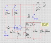
Why use back to back zeners, instead of LM329I took the liberty of doing some sims of a slightly modified circuit. Replaced the 1K5 resistor with a constant current source and the LM329 with back to back zeners.
Load-line regulation
View attachment 1213895
PSRR
View attachment 1213896
Output impedance
View attachment 1213897
View attachment 1213898
Noise
View attachment 1213899
Its familiar. Specify the design, and accept the performance (the road to hell).
Or, specify the performance, accept the design (the road to heaven).
But there's nothing wrong with specifying the design and accept whatever performance you can get, this is diyaudio after all, the purpose is to have fun!
As Nelson would say, 'It's entertainment, not dialysis!' .
Jan
Or, specify the performance, accept the design (the road to heaven).
But there's nothing wrong with specifying the design and accept whatever performance you can get, this is diyaudio after all, the purpose is to have fun!
As Nelson would say, 'It's entertainment, not dialysis!' .
Jan
If you add a startup Zener to the .asc of post #24, you can connect the Vref circuit in what Walt Jung and Jan Didden call "bootstrapped" configuration: Bias current for the Vref diodes, is drawn from the regulator output not the regulator input. It's one of the things that makes the Super Regulator, so Super.
The drain of "J1" is moved from In to Out.
The drain of "J1" is moved from In to Out.
Control by voltage, so stable output at large output currents with a simple circuit. Though, high Ciss requires decent gate current available for fast changes or good transient response. It's easy to design compact regulator for 10 or even 20 A.Generally speaking what feature is the advantage of a Mosfet versus a Bjt pass transistor.
Since it's 20V input and 15V output, you have a large amount of voltage headroom, which you can trade off to get much better PSRR. Especially since the output current is only 100mA.
You could buy (this 10 ohm 2 watt 1% resistor) for USD 0.45 and (this 2200 microfarad, 25 volt, 2.88A ripple current, electrolytic capacitor) for USD 0.75. Connect them as an RC lowpass filter, upstream of the discrete regulator circuit. 20V input --> RC lowpassfilter --> discrete regulator --> 15V output. You will see a dramatic improvement in PSRR, especially at frequencies above 100 Hz. At a cost of USD 1.20.
You could buy (this 10 ohm 2 watt 1% resistor) for USD 0.45 and (this 2200 microfarad, 25 volt, 2.88A ripple current, electrolytic capacitor) for USD 0.75. Connect them as an RC lowpass filter, upstream of the discrete regulator circuit. 20V input --> RC lowpassfilter --> discrete regulator --> 15V output. You will see a dramatic improvement in PSRR, especially at frequencies above 100 Hz. At a cost of USD 1.20.
Indeed Mark. We should realize that the output ripple of a regulator is not a fixed number, but depends on the input ripple. The regulator only attenuates it.
So, as Mark noted, one way to lower the output ripple is to lower the input ripple with an extra low pass formed by an R and a C. You will lose some voltage across the R, but with high headroom and low load current, you can afford it.
Jan
So, as Mark noted, one way to lower the output ripple is to lower the input ripple with an extra low pass formed by an R and a C. You will lose some voltage across the R, but with high headroom and low load current, you can afford it.
Jan
This would be great if it was variable +/-50V for use as a power amp test supply but for a fixed +/15V supply, there are many quick and easy solutions. A while back, I posted my little ~op-amp test supply that I built many years ago. It was a +/- tracking variable 0~17V supply that fit in a little Radio-Shack plastic box. I used it a lot. I'm looking for those files and will post it when I find them. The attached simulation uses the same idea.
Attachments
I did like you suggest.Since it's 20V input and 15V output, you have a large amount of voltage headroom, which you can trade off to get much better PSRR. Especially since the output current is only 100mA.
You could buy (this 10 ohm 2 watt 1% resistor) for USD 0.45 and (this 2200 microfarad, 25 volt, 2.88A ripple current, electrolytic capacitor) for USD 0.75. Connect them as an RC lowpass filter, upstream of the discrete regulator circuit. 20V input --> RC lowpassfilter --> discrete regulator --> 15V output. You will see a dramatic improvement in PSRR, especially at frequencies above 100 Hz. At a cost of USD 1.20.
Input filter: 2R2 + 10000uF
PSRR:
100Hz - 112dB ...previous 90dB
10kHz - 110dB ...previous 49dB
That is a big difference!
Maybe this transformer for +/-50V regulator:
https://www.toroidal-transformer.co...va/118/2x-40v-toroidal-transformer-500va.html
https://www.toroidal-transformer.co...va/118/2x-40v-toroidal-transformer-500va.html
- Home
- Amplifiers
- Power Supplies
- Discrete Regulators +/-15V with good performance