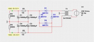
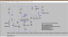
First.
To feed the regulators you need a 2x15VAC transformer and rectifiers.
See first image.
The discrete regulators for positive/negative uses 5 transistors each.
The negative regulator is a mirrored circuit.
Test run shows very good data and precision thanks to 2 current sources.
To feed the regulators you need a 2x15VAC transformer and rectifiers.
See first image.
The discrete regulators for positive/negative uses 5 transistors each.
The negative regulator is a mirrored circuit.
Test run shows very good data and precision thanks to 2 current sources.
Attachments

Impedance traces, line regulation, load regulation, noise, current capacity and PSSR - we want to know the characteristics if the 2 (+ & -) devices please.
And the lingering question.... is it better then LT3045? 😉
//
And the lingering question.... is it better then LT3045? 😉
//
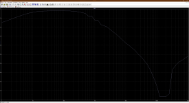
I will post some data to show how good regulators are.
PSRR, power supply rejection ratio.
At 20V input and 100mA load:
100 Hz: -109 dB
1 kHz: -92 dB
PSRR, power supply rejection ratio.
At 20V input and 100mA load:
100 Hz: -109 dB
1 kHz: -92 dB
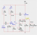
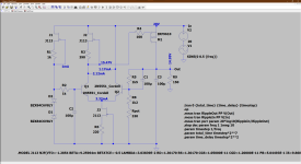
Here is the new version.
More powerful MOSFET makes 5A and more output.
Also both Line and Load regulation is improved.
PSRR at 100 Hz is 98dB
PSRR at 1kHz is 78dB

More powerful MOSFET makes 5A and more output.
Also both Line and Load regulation is improved.
PSRR at 100 Hz is 98dB
PSRR at 1kHz is 78dB
As this is a lowdrop Regulator it will work very well even at 15.2V input.
Test of Line Regulation.
Line Regulation with 100mA load.
25.0 Vin: 15.0001
22.0 Vin: 15.0000
20.0 Vin: 15.00000
18.0 Vin: 15.0000
16.0 Vin: 14.9999
15.5 Vin: 14.9999
15.2 Vin: 14.9999
Line Regulation with 1A load.
25.0 Vin: 15.0001
22.0 Vin: 15.0000
20.0 Vin: 15.00000
18.0 Vin: 15.0000
16.0 Vin: 14.9999
15.5 Vin: 14.9999
15.2 Vin: 14.9997
Test Load Regulation. How well regulation is with different, varying load.
With 20V input it works excellent. In all loads.
Also with 15.5V input it is good. With one exception: 5A load.
5A load needs like 16V input.
Load Regulation at 20V input.
0.01 A Load: 15.0000
0.02 A Load: 15.0000
0.05 A Load: 15.0000
0.10 A Load: 15.00000
0.20 A Load: 15.0000
0.50 A Load: 14.9999
1.00 A Load: 14.9999
2.00 A Load: 14.9998
5.00 A Load: 14.9996
Load Regulation at 15.5V input.
0.01 A Load: 15.0000
0.02 A Load: 15.0000
0.05 A Load: 15.0000
0.10 A Load: 15.00000
0.20 A Load: 15.0000
0.50 A Load: 14.9999
1.00 A Load: 14.9999
2.00 A Load: 14.9997
5.00 A Load: 14.8584
Load Regulation at 16V input.
5.00 A Load: 14.9995
Line (load) regulation "should" also be tested with a step in the load i.e. not a staty state test. It's like a transient test.
How much noise do these regulators generate?
What is the output impedance? ohm vs frequency please?
//
How much noise do these regulators generate?
What is the output impedance? ohm vs frequency please?
//
Maybe you could also describe a bit of the idea behind the design and describe how the good performance is achieved?
//
//
The design is straightforward and does not need explanation.
But which drawing program is used and does it contain tubes ?
But which drawing program is used and does it contain tubes ?
Mouser sells 2200uF 25V electrolytic capacitors for less than 1.00 USD. You could pair that with a 10 ohm resistor to make a lowpass pre-filter before the regulator, giving you an additional 20dB of line rejection ("PSRR") at 100 Hertz. It would also reduce the VDS across your output MOSFET by (10 * 0.1) = 1.0 volts.
Or if you are willing to spend even more money, for additional 0.50 USD you could connect a Bourns RLB0914-102KL inductor in series with the resistor, now giving yourself an R-L-C lowpass filter with good line rejection at 100 Hz and tremendous line rejection at 1000 Hz. Since the inductor's series resistance is 2.1 ohms you'd drop the fixed resistor's value to approx 8.2 ohms, in order to keep the total resistance around 10 ohms and the voltage drop around 1 volt.
You can ask your circuit designer to explore these proposed modifications in a circuit simulation program like SPICE, to find out how much line rejection you'll achieve (without, and then with, the modifications). Then the two of you can decide whether it is a good use of 1.50 USD to add the changes.
This looks like NI MultiSim. It does have some tubes in it. And you can supply your own SPICE models as well.But which drawing program is used and does it contain tubes ?
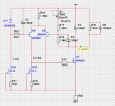
To reduce noise you can replace LM329 for two zeners.
And reduce R2 from 1k to 270ohm.
https://refsnregs.waltjung.org/The_PM829_Reference.pdf
And reduce R2 from 1k to 270ohm.
https://refsnregs.waltjung.org/The_PM829_Reference.pdf
The easiest way to reduce noise is to increase the RC timeconstant of the lowpass filter between the LM329 and the opamp. Or, for even greater noise reduction, subdivide it into an RCRC ladder plus shrewdly calculated partitioning. This will reduce higher frequency noise dramatically.
Last edited:
I took the liberty of doing some sims of a slightly modified circuit. Replaced the 1K5 resistor with a constant current source and the LM329 with back to back zeners.
Load-line regulation

PSRR

Output impedance


Noise

Load-line regulation
PSRR
Output impedance
Noise
Attachments


Walt Jung (and I) would recommend that you increase R2. Walt's recommendation is R2=5.6K, but he envisions implementations where R8 is fixed and unchangeable, and "Rpot" does not exist. Seeing that you do include "Rpot", I strongly recommend R2=22K. Which is even larger.
Also I would suggest that you think very hard about why you use an approximately-constant-current-source at the tail node of a diff amp whose input is a fixed, constant, unchanging, stable DC voltage. There is no common mode input signal hence no need for wonderful CMRR. In what way is the CCS implementation superior to a simple resistor between the emitter tail node, and ground? Why spend the parts cost and the board area? Are you simply copying someone else's design, imagining & hoping that they know more than you know?
Also I would suggest that you think very hard about why you use an approximately-constant-current-source at the tail node of a diff amp whose input is a fixed, constant, unchanging, stable DC voltage. There is no common mode input signal hence no need for wonderful CMRR. In what way is the CCS implementation superior to a simple resistor between the emitter tail node, and ground? Why spend the parts cost and the board area? Are you simply copying someone else's design, imagining & hoping that they know more than you know?
- Home
- Amplifiers
- Power Supplies
- Discrete Regulators +/-15V with good performance