Wangine in Taiwan did a jfet input version of the 990 more than 20 years ago for a Parasound preamp Called the P-Fet 900, I think.
It might be interesting to offer an update since the devices specified are listed as obsolete. I found it funny that Pete also discovered Dick Burwen's work, 46 years old. I think basicly the discrete op-amp ground was well covered 40 yr. ago.
They aren't noiseless, but they are not too bad. However the manufacturer of those depletion-mode devices offers no data, no guarantees, and they are sole-sourced. Not a bother for diy but the devil for production.In one of Walt Jung's articles he expounds the virtues of virtually noisless mosfet constant current sources. Ray
Also as bcarso points out there might be an opportunity for power on latch-up so there might be a simple clamp needed somewhere. I don't think this is a big problem.
That apparent problem was I suspect just an artifact of initialization with an ideal buffer, one with unlimited output voltage swing. However, some worst-case rail sequencing and heavy overloading should probably be done before we go into production 🙂
latch-up
Often (not always) power on latch up can be handled by assuring both + and - supplies come up together. Often this complicates a dual reg supply design. This can be done many ways but the simplest way (thus my favorite) is to use a large value cap across the + and - rails.
As a byproduct, it cancels differential mode noise and aids in keeping the two rail voltages equal.
Last edited:
For traditional regulated dual-rail supplies I usually have one reference voltage with lots of filtering determine the one rail, and a equal R voltage divider from that output to the other output be the complementary rail's output feedback, with common as the other error amp voltage. By the time the first reference comes up, both of the unregulated inputs have stabilized, so the overall effect is orderly symmetrical ramps on both outputs.Often (not always) power on latch up can be handled by assuring both + and - supplies come up together. Often this complicates a dual reg supply design. This can be done many ways but the simplest way (thus my favorite) is to use a large value cap across the + and - rails.
As a byproduct, it cancels differential mode noise and aids in keeping the two rail voltages equal.
I just love it when Scott puts up a circuit! This refinement on the first is a Very nice blend of volt and current feedback concepts. Still flexible re adjusting open/closed loop gain for DIY'ers to play with to learn about that issue. I was happy with the first design put up. Now this! Its getting dialed in... wont be long now (?) and we can build something. 🙂 Thx -RNM
Scott,
Being a complete newbie here and trying to follow what I can here I'm am lost as to the feedback circuit. Where does the r6 and r12 get in the circuit?
Being a complete newbie here and trying to follow what I can here I'm am lost as to the feedback circuit. Where does the r6 and r12 get in the circuit?
What seems to be lost here, is: WHAT IS IMPORTANT? Of course, many discrete op amp design ideas were developed more that 40 years ago, but not all! The OPTIMUM designs are usually elegant, as well as relatively easy to source parts, etc. Unfortunately, then the OPTIMUM design changes with source availability, as well as added circuit tricks.
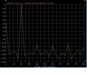
What is important is how linear and/or how quiet the circuit is, how fast, etc.
What is important is how linear and/or how quiet the circuit is, how fast, etc.
A *real* opamp needs to start with a Telefunken ECC83 marked "GAP/R". The rest just follows! (Or a 6SL7 for traditionalists).
Thanks,
Chris
Thanks,
Chris
A *real* opamp needs to start with a Telefunken ECC83 marked "GAP/R". The rest just follows! (Or a 6SL7 for traditionalists).
Thanks,
Chris
Or a 6C4.
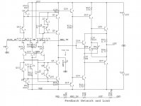
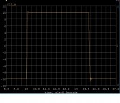
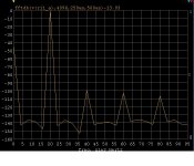
What do we assume for source impedance?OK here is the Rush cascode version 200V/us into 600 Ohms not to shabby.
Dick Burwen
Well, didn't he design most of the Cello line? It's a favored mastering tool in many recording studios. And some of those transistors go back to the 60s. I would think that transistor manufacture has improved with getting the impurities out of the silicon sandwich in 40 years. I know they don't want to make discreet devices. RayIt might be interesting to offer an update since the devices specified are listed as obsolete. I found it funny that Pete also discovered Dick Burwen's work, 46 years old. I think basicly the discrete op-amp ground was well covered 40 yr. ago.
I think that Tom Colangelo designed most of the Cello circuits. It is interesting to see how Mark L. tries to re-write history. Apparently, neither Tom or I am an interesting or important part in Mark's history, anymore.
Dick Burwen designed the original LMP-2, LNC-2 for Mark Levinson Audio Systems, then much later, designed the Cello equalizer. Dick Burwen has been a believer in IC's since the early 70's, almost exclusively. He DID design good discrete op amps for AD back in the '60's, but he converted over, early. In fact, that is why I was able to take over design at MLAS, for a couple of years. I designed sophisticated discrete designs, that Mark found sounded better than selected IC's at the time.
Dick Burwen designed the original LMP-2, LNC-2 for Mark Levinson Audio Systems, then much later, designed the Cello equalizer. Dick Burwen has been a believer in IC's since the early 70's, almost exclusively. He DID design good discrete op amps for AD back in the '60's, but he converted over, early. In fact, that is why I was able to take over design at MLAS, for a couple of years. I designed sophisticated discrete designs, that Mark found sounded better than selected IC's at the time.
Scott,
Being a complete newbie here and trying to follow what I can here I'm am lost as to the feedback circuit. Where does the r6 and r12 get in the circuit?
Just connect the node labels, I am trying to make the schematics easy to read without a lot of crossing wires.
What do we assume for source impedance?
I know that's an issue, but it's good to start at a baseline and work from there.
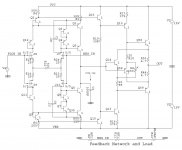
One last one for today, the fully complimentary version. If SK170/SJ74 FET's are used high source impedances are not recommended.
Attachments

Last edited:
I swear, Scott! Can't you design a SIMPLE but ELEGANT circuit? '-) Discrete devices are NOT FREE, you know.
Last edited:
I would not use 600 Ohms for a source Z. I think 100 ohms is a best fit compromise for a standard.
[ Or lower]
[ Or lower]
Last edited:
There's various types of latch up behaviour.Also as bcarso points out there might be an opportunity for power on latch-up so there might be a simple clamp needed somewhere. I don't think this is a big problem.
TL07x will go "bang, bang" to each rail on startup but are normally OK after that .. even on simple single supply circuits.
Far nastier is LM4562 which will latch and not let go on many simple single supply circuits.
Both have *!?@!" overload behaviour on certain HP filter circuits.
You can get round these with some extra circuit complexity but usually the best solution is to use another OPA.
_____________________________
Is there a list of requirements for this project somewhere?
- Home
- Source & Line
- Analog Line Level
- Discrete Opamp Open Design