I prefer minimal series thru-path, BUT not minimum active parts for its own sake. IF you create an arbitrary maximum of active devices, you reduce the field of choice AND the potential optimization of any particular circuit. I think that Einstein said something like:
Everything should be made as simple as possible, but no simpler. '-)
Everything should be made as simple as possible, but no simpler. '-)
Last edited:
OK. So, make opamp as good as possible and as simple as possible. but no simpler.
Now where were we??
Now where were we??
...that's a matter of taste.
To me our OP amp discussion has moved to much to high component count.
I like Gerhard's idea to settle an symmetric version of the LinuxBuffer.
Unfortunately my understanding how to symmetrize the buffer leads to
higher component count than Gerhard's schematic...
Just a thought, but not simulated.
To me our OP amp discussion has moved to much to high component count.
I like Gerhard's idea to settle an symmetric version of the LinuxBuffer.
Unfortunately my understanding how to symmetrize the buffer leads to
higher component count than Gerhard's schematic...
Just a thought, but not simulated.
Attachments
...that's a matter of taste.
To me our OP amp discussion has moved to much to high component count.
I like Gerhard's idea to settle an symmetric version of the LinuxBuffer.
Unfortunately my understanding how to symmetrize the buffer leads to
higher component count than Gerhard's schematic...
Just a thought, but not simulated.
Symmetry IS important.
Last year I was making just a buffer to entertain myself and was up to 12 transistors and heading towards more before I said - 'stop'. Way too many transistors.... but the distortion was unmeasureable (really low). IMO I decided for myself that the lowest harmonic content couldnt be the only goal. What other parameters make for a better audio circuit besides noise, IM and harmonic content? How important is CMR in audio? PSR is important but can be divided between power supply and circuit.
Last edited:
With +/- 24 VDC supplies, a final stage of supply decoupling might be included in the package. Maybe even with a professional +24 dbu output? It's a good place to put a final supply decoupler anyhoo.
Thanks,
Chris
Thanks,
Chris
I prefer minimal series thru-path, BUT not minimum active parts for its own sake. IF you create an arbitrary maximum of active devices, you reduce the field of choice AND the potential optimization of any particular circuit. I think that Einstein said something like:
Everything should be made as simple as possible, but no simpler. '-)
Agree . Minimize the through path, but the supporting cast should be as required. Damn the expense LOL.
Agree . Minimize the through path, but the supporting cast should be as required. QUOTE]
I agree, too. I count a cascode as one and dont count CCS et al.
John. You just did IT? What does - you just did it mean?
Whats the best power supply topology... series or shunt reg or both?
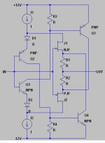
Well, I don't know what I mean, Richard, except that to remove active parts from my example schematic would compromise it, somewhat. However, many here would add 10 more active devices in the follower stage, etc. I do shake my head at that.
By the way, this design would not need a servo if the gain were reduced to headphone levels, if that bothers you. '-) Just use a monolithic dual fet at the input.
By the way, this design would not need a servo if the gain were reduced to headphone levels, if that bothers you. '-) Just use a monolithic dual fet at the input.
Attachments

Last edited:
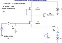
I combined Scott's cascoded gain stage with my CCB, and it sims Ok. I kludged in a pair of PNPs instead of P-JFETs in the LTP, and it doesn't appear to hurt.
THD20 sims at -95 dBr at 4V into 600R, without much optimization. GBW is 25 MHz, small-signal.
THD20 sims at -95 dBr at 4V into 600R, without much optimization. GBW is 25 MHz, small-signal.
Attachments
I combined Scott's cascoded gain stage with my CCB, and it sims Ok. I kludged in a pair of PNPs instead of P-JFETs in the LTP, and it doesn't appear to hurt.
THD20 sims at -95 dBr at 4V into 600R, without much optimization. GBW is 25 MHz, small-signal.
Curious... open loop BW and gain is ______ ?
Curious... open loop BW and gain is ______ ?
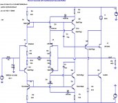
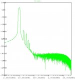
You can resistively load the high gain node to ground to give you any OLBW you want (within reason). I admit it is a sideshow but this circuit makes it easy to explore the issue, (no R ) Aol = ~120dB and BW = 50Hz and does it matter if you reduce it to 66dB and 20kHz?
I found it interesting that George Wilson presented an all NPN and NJFET op-amp in >>1968<< that had 200V/usec slew rate and 50MHz BW. This WAS potentially good for audio but I never saw any followup.
Yup, the same Wilson as in the current mirror.
Yup, the same Wilson as in the current mirror.
Did match a few JFETs, and put them in the circuit in #945 - interestingly enough, got overall better DC balance and drift as expected, but THD raised quite bit: still < 0.001% @ 0dBV, 1 kHz into 30 ohm, with 2nd accounting for most of the raise. Seems that the best operating point as far as the DC balance is concerned is not the point of best AC symmetry (unless the very low figures I got a few days ago were due to some lucky cancellation effects...). Sounds anyway a little bit strange: what am I missing?
L.
L.
You can resistively load the high gain node to ground to give you any OLBW you want (within reason). I admit it is a sideshow but this circuit makes it easy to explore the issue, (no R ) Aol = ~120dB and BW = 50Hz and does it matter if you reduce it to 66dB and 20kHz?
A trick I used when playing with discrete CFA, but it seems a purely cosmetic effect, isn't it? Once OLG @ 20 kHz is fixed, I think there's no point in deliberately lowering it at LF just to get a flat OLBW - 120 dB @50 Hz and 70 dB @ 20 kHz is better than 70 dB from 50 Hz up to 20 kHz...
L.
Have you ran a curve trace of both to see how closely they are complimentary?Did match a few JFETs, and put them in the circuit in #945 - interestingly enough, got overall better DC balance and drift as expected, but THD raised quite bit: still < 0.001% @ 0dBV, 1 kHz into 30 ohm, with 2nd accounting for most of the raise. Seems that the best operating point as far as the DC balance is concerned is not the point of best AC symmetry (unless the very low figures I got a few days ago were due to some lucky cancellation effects...). Sounds anyway a little bit strange: what am I missing?
L.
If you make Q3, Q4 as folded cascodes you could couple in into the positive and negative side without criss crossing. Maybe it will have higher speed too.
- Home
- Source & Line
- Analog Line Level
- Discrete Opamp Open Design