lineup said:😉
Elvee
What kind of JFET is 2N4117.
I have never heard of that one.
Never seen it for sale here in Europe or in my country.
I get it is a N-JFET.
The only thing special about the 2N4117 is the fact that it's one of the rare low power JFET to be present in the standard libraries of LTspice; I've to confess that unlike Suzy, I'm somewhat lazy and I only import/tweak models when there is really no other option...
Any small geometry JFET can do, obviously the ones specifically designated by the manufacturer to be low noise are preferable, but the circuit will work with any FET having a c.o. voltage of around 1V, BF245A or BC264A if you like european denominations.
You could even use a 2N3819, the only adverse effect being an output shifted in the positive direction wrt. to the 4.5V reference.
Operating transistors at low currents has no adverse effect, unless you grossly overdo it, or when you need speed. Here, the voltage swing at the drain of J1 is minuscule and 3µA is quite sufficient, even taking into account the Miller effect from the Bjt (at least for an audio bandwidth).
LV
PS: even run-of-the-mill bipolars can operate at unbelievably low current levels: have a look at this site, you'll be convinced:
http://www.techlib.com/science/ion.html
(go to mid page)

Elvee said:
Looks like this thread is becoming an on-line contest:
Mine is bigger than yours;
boy's stuff; I'm sure suzywill love it.

Sorry, I just cant help myself. Especially when spiked with all that sugar and caffine.
lineup said:
( Are you really a woman??
Yes, I think I did see some picture of you, with your interesting bikes)
Sorry, OT:
Now, "bikes" made me look at your site.
But I didn't read a lot cause it's too late now. Did you have a good teacher to make frames? I knew a renown frame maker (at least around here 🙂 ) and it seemed pretty difficult to build a light frame well, so it lasts long...
Whenever you really come to Europe to participate at "Paris-Brest-Paris", mail me before, I'll recommend you some other fun (probably more fun than the above) tours.
Now, back to Transistors...
Cheers,
Dominique
Elvee said:
Looks like this thread is becoming an on-line contest:
Mine is bigger than yours;
boy's stuff; I'm sure suzy
<grin> I'm having a hoot of a time.
Elvee, you're a genius. I'll see your circuit and raise you two transistors:
0.11% THD (1KHz 6Vpp into 10K Ohms)
0.002% THD (1 KHz 100mVpp into 10K Ohms)
89uA Iq
9.5dB gain
10Hz to 100KHz bandwidth
2.3M Ohm Zin
An externally hosted image should be here but it was not working when we last tested it.
Cheers,
Suzy
Suzy,suzyj said:Yes, it is. if I keep the quiescent current down to 200uA, that means I can get around 2500 hours (3 months) operation from a 9V PP3 alkaline battery (500mAh). I'll arrange it so that the battery is disconnected when I remove the lead from the guitar, so the battery lifetime should be quite long.
The idea of this circuit is to buffer the pickups. In this application, I don't think that adding distortion is helpful. Certainly, really low distortion isn't necessary, but it isn't that hard to get, either 🙂
Cheers,
Suzy
From experience (most of my basses are active) the reality is it's just best to change batteries every 6 months or so to avoid any difficult moments on stage. You could also use a 3 conductor cable and power it offboard which removes any issues with trying to fit a battery into your guitar and greatly expends the possibility for circuit design as you'll not need to worry about current draw / battery life at all. Add a pot with a DPDT switch to bypass to passive for emergencies if you so desire, but I've never run into any issues remotely powering in many years of doing it, eg with my Alembic Series 1 which is powered offboard (and has been since it was built in 1980).
I'd also go with a simpler circuit if you simply want to buffer the pups, something like a single J201. You should try it at least first.
Attachments
Brett said:Suzy,
I'd also go with a simpler circuit if you simply want to buffer the pups,
something like a single J201.
You should try it at least first.
.
I agree with Brett.
Even if nice to see such fine and great low power amplifiers here,
I like the original idea by suzyj, the best.
With minor adjustments circuit posted in beginning of this topic
would be very good = good enough for the job.
Any circuit using more than 2T is in my opinion
an overkill for this job.
But sure is great fun to test the limits of amplifier design 😉
And what is bad with some competition, contest ???
Should we forbid Football, Formula One, NHL ICE-hockey and Olympic games ????
This is what people really like. Yes even love!
A good nice competition or a race at the tracks, including some betting.
And those more advanced ( read more than 4T ) winning circuits contributions
can become useful some time in some other applications.
Regards
lineup 😎
suzyj is an engineer
and
... signed up for PhD in electronic at university, which she's currently working on part-time.
So I better watch out,
before saying anything stupid regarding circuitry.
😀
Not that I think suzyj would make fun of me,
or push me down because I had gotten something wrong,
as some few likes to do here at forum, at times.
I deserve respect, as well as anybody else.
Even our 'newbies' deserves to be treated fairly.
-------------------------
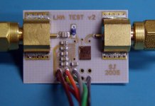
I do not know if image attached
is one chip actually designed by suzyj,
but
the topic starter here probably can do some tests like this, in some of her time
Regards
lineup - far from an engineer, but certainly not ignorant, about audio circuits
😉
and
... signed up for PhD in electronic at university, which she's currently working on part-time.
So I better watch out,
before saying anything stupid regarding circuitry.
😀
Not that I think suzyj would make fun of me,
or push me down because I had gotten something wrong,
as some few likes to do here at forum, at times.
I deserve respect, as well as anybody else.
Even our 'newbies' deserves to be treated fairly.
-------------------------
I do not know if image attached
is one chip actually designed by suzyj,
but
the topic starter here probably can do some tests like this, in some of her time
Regards
lineup - far from an engineer, but certainly not ignorant, about audio circuits
😉
Attachments

Daveis said:Which of these circuits has the lowest 3rd and higher order harmonic distortion?
RIght question! 🙂
G.Kleinschmidt said:Like Bart Simpson says - eat my shorts!
Hey, yer cheating! No fair using constant current source components - ya gotta build it out of discretes. I figure that'll add at least 20uA Iq 🙂
Seriously though, this is a neat exercise. It's been heaps of fun trying to squeeze as much performance as possible out of every microamp.
I note you're sticking with bipolars in the front end. Any reason for this? I've always just assumed that high input impedence dictates some sort of FET input.
lineup said:So I better watch out,
before saying anything stupid regarding circuitry.
Hey, I'm probably a lot more likely to say stupid things than many of the people here, yourself included. I've learnt heaps in the months I've been participating in these forums.
Cheers,
Suzy
Wavebourn said:RIght question! 🙂
The electric guitar is a "thin" sounding instrument with a range of maybe 41hz (bass) to under 5khz.
In my estimation the best of the circuits presented would have
a) 2nd harmonic no more than 1%
b) 3rd harmonic at least 10-20db lower than 2nd harmonic
c) 4th and higher harmonics 40db lower than 3rd and as low as possible.
You've been heading the wrong direction.... the right kinds of distortion are GOOOD... their better than good, their GREAT.
Guitarists pay BIGGGGGG dollars for little stomp boxes with the opamp that gives them the sweetest distortion.
I've noticed that some of the nicest sounding tube amps are all single-ended class-A. Would that mean that a SonofZen-style preamp maybe would meet my criteria for what _should_ sound nice?
Wavebourn, Oh, I didnt mean you.
I had been following the circuit postings. Each one seemed to be designed to give ever lower THD. I was advocating that the friendly competition here turn towards concentrating on eliminating higher order distortion. 2nd harmonic in a guitar application is fairly benign.
Recently, at a friends place I listened to his tone. He was using an MXR90 phaser, Ibanez tube screamer, Jekyll and Hyde distortion and a Mesa Boogie amp. He was getting a decent tone, but I couldn't help but think about all the cheap little opamps in his gear. And yet, he could get some decent sounds out of his rig.
I don't see why a guitar preamp couldnt introduce a little bit of it's own tone/distortion as long as it's pleasant sounding.
I'll be quiet now.... since I haven't built and listened to any of the circuits proposed. They all probably sound great.
Daveis said:Wavebourn, Oh, I didnt mean you.
I had been following the circuit postings. Each one seemed to be designed to give ever lower THD. I was advocating that the friendly competition here turn towards concentrating on eliminating higher order distortion. 2nd harmonic in a guitar application is fairly benign.
---------
I don't see why a guitar preamp couldnt introduce a little bit of it's own tone/distortion as long as it's pleasant sounding.
I'll be quiet now.... since I haven't built and listened to any of the circuits proposed. They all probably sound great.
I have said I like those more simple versions, contributed here.
Max 2T, two transistors.
And I find Daveis is right.
Guitar is a musical instrument.
Like eventual resonances, harmonics created in a the body of a violin or a piano
an electric guitar with its electro magnetics and electronics
are to be seen upon as one unit.
The total output from this, is 'the sound' of guitar.
Sometimes with added soft/hard clipping and distortion harmonics.
How much % THD is that??????????
So, yes,
making things advanced here, going for ZERO DISTORTION
may be a 'catch the wind' operation.
Lots of fuzz 😀 for very little really gained!
suzyj initial goal is reasonable
but already this may be a case of overdoing this design.
I repeat my opinion from post above:
Go for something fairly simple and nice.
And if it works and you like what your hear,
be pleased and satisfied with your little amp.
lineup
suzyj said:
Hey, yer cheating! No fair using constant current source components - ya gotta build it out of discretes. I figure that'll add at least 20uA Iq 🙂
Aww, C'mon. You could get away with 10uA easy

Seriously though, this is a neat exercise. It's been heaps of fun trying to squeeze as much performance as possible out of every microamp.
I note you're sticking with bipolars in the front end. Any reason for this? I've always just assumed that high input impedence dictates some sort of FET input.
You don’t necessarily need FETs for high input impedance – it all depends on the circuit topology. For a start, we’re running at such low currents here, the base currents of the BJTs are low enough to still allow large value biasing resistors without introducing major voltage offsets. Also, in that last circuit of mine, the input bias current of the NPN differential pair transistors is mostly cancelled out by the input bias current of the PNP differential pair, which flows in the opposite direction. In reality though, there will always still be some input bias current, as the hfe of the PNP transistors will never perfectly match that of the NPN transistors.
Now as for the input impedance; the input resistance of a BJT with its emitter tied to ground is approximately equal to the emitter resistance (0.026/Ic) multiplied by the transistors beta. At 10uA Ic, this gives maybe a couple of hundred kilohms or so of input resistance for your average 20 cent small signal transistor – still a long way off several megohms though!
However as part of a differential pair, the emitter is not tied to ground - it is tied to the emitter of the other transistor forming the differential pair. We can ignore the contribution of the constant current tail, as its impedance is theoretically infinite. It isn’t infinite in reality, but it’s still so high that we can ignore it anyway.
If you were to analyse the operation of the basic non-inverting op-amp topology we’re using here, you’d find that by virtue of the negative feedback and high open loop gain, the actual differential AC voltage between the bases of the two transistors forming the input differential pair is very, very tiny, while the common mode voltage is quite large.
This means that the series connected internal emitter resistances of the transistors forming the differential input pair are effectively bootstrapped, sending the beta multiplied input impedance right through the roof.
The input impedance for that circuit of mine is therefore effectively governed by the two 4.7M input biasing resistors. Nifty huh? 🙂
Cheers,
Glen
Daveis said:Wavebourn, Oh, I didnt mean you.
Pitty...

I hoped you can show really better road...
I had been following the circuit postings. Each one seemed to be designed to give ever lower THD. I was advocating that the friendly competition here turn towards concentrating on eliminating higher order distortion. 2nd harmonic in a guitar application is fairly benign.
Recently, at a friends place I listened to his tone. He was using an MXR90 phaser, Ibanez tube screamer, Jekyll and Hyde distortion and a Mesa Boogie amp. He was getting a decent tone, but I couldn't help but think about all the cheap little opamps in his gear. And yet, he could get some decent sounds out of his rig.
I don't see why a guitar preamp couldnt introduce a little bit of it's own tone/distortion as long as it's pleasant sounding.
I'll be quiet now.... since I haven't built and listened to any of the circuits proposed. They all probably sound great.
I agree with you that if you can't avoid some colorations you'd better make them pleasant. But why do you need'em at all? Remember, a guitar has more than one string, and intermodulation is not desirable. Lead guitar is another story. When you pick oscillations of iron strings on a peace of wood and plastic by coil and magnet you loose "soul"; in such case additional level dependent distortions and filtering makes the sound more alive. In case of acoustic guitar the sound is already rich and alive, so class A single ended amp is the way to preserve this life and richness. Symmetrical emitter follower output kills this life adding increasing level of distortions and abrupt decay on very low levels of signal. I agree with you that the less is level, the less distortions are allowable (not desirable, it is another story).
Daveis said:Wavebourn, Oh, I didnt mean you.
I had been following the circuit postings. Each one seemed to be designed to give ever lower THD. I was advocating that the friendly competition here turn towards concentrating on eliminating higher order distortion. 2nd harmonic in a guitar application is fairly benign.
Recently, at a friends place I listened to his tone. He was using an MXR90 phaser, Ibanez tube screamer, Jekyll and Hyde distortion and a Mesa Boogie amp. He was getting a decent tone, but I couldn't help but think about all the cheap little opamps in his gear. And yet, he could get some decent sounds out of his rig.
I don't see why a guitar preamp couldnt introduce a little bit of it's own tone/distortion as long as it's pleasant sounding.
I'll be quiet now.... since I haven't built and listened to any of the circuits proposed. They all probably sound great.
I think you're missing the point here. The aim is to simply make a low distortion line driver which doesn't add any appreciable coloration to the sound of the guitar - desirable coloration or not. Distortion effects and coloration call all be properly done in the guitar amplifier.
Any yes, the circuits here are a bit of an overkill, but that's just for fun.
G.Kleinschmidt said:The aim is to simply make a low distortion line driver which doesn't add any appreciable coloration to the sound of the guitar - desirable coloration or not.
...and get The Nobel Prize! 😉
- Status
- Not open for further replies.
- Home
- Live Sound
- Instruments and Amps
- Discrete guitar preamp