So the latest circuit is a buffer with no voltage gain?
I've heard of active EQ put into acoustic guitars.
The output of the guitar pickup is millivolts and high impedance. I can see increasing the voltage at the source so that the S/N of any picked up noise is small.
But all my guitar amp equipment assumes it's being driven by the guitar directly. What effect would a preamp do for me?
Daveis said:So the latest circuit is a buffer with no voltage gain?
The simplest ones are buffers (eg http://www.diyaudio.com/forums/showthread.php?postid=1075612#post1075612).
The one I'm building (http://www.diyaudio.com/forums/showthread.php?postid=1077620#post1077620 ) has 10dB gain as presented, but of course can be pretty much anything.
Daveis said:I've heard of active EQ put into acoustic guitars.
The output of the guitar pickup is millivolts and high impedance. I can see increasing the voltage at the source so that the S/N of any picked up noise is small.
But all my guitar amp equipment assumes it's being driven by the guitar directly. What effect would a preamp do for me?
The input impedence of your amp or effect box is high impedance (it has to be). However the output of a normal pickup is also very high impedance (to get as much voltage as possible without taking excessive energy from the string and damping it).
What this means is that parasitic capacitance (for example by using a long lead between the guitar and amp) reduces the high frequencies, and changes the tone of the guitar.
If you put a buffer at the pickup, you both minimise stray noise and RFI picked up on the cable, and also ensure that the signal at the pickups makes it through to the other end without the high frequencies being clobbered.
That's without gain. With gain, you can improve the S/N ratio, and if you use a pickup with fewer turns, you can get better sustain.
Cheers,
Suzy
A schematic:
And a PCB:
It'll be a little while before further progress is made, as I've got a few more bits to go out at the same time.
Cheers,
Suzy
An externally hosted image should be here but it was not working when we last tested it.
And a PCB:
An externally hosted image should be here but it was not working when we last tested it.
An externally hosted image should be here but it was not working when we last tested it.
It'll be a little while before further progress is made, as I've got a few more bits to go out at the same time.
Cheers,
Suzy
Neat layout!
Amidst the protests of over complexity, that finalised board layout finally puts things into perspective – a tiny 15x32mm and only a few dollars worth of semiconductors. Big deal!
Cheers,
Glen
Amidst the protests of over complexity, that finalised board layout finally puts things into perspective – a tiny 15x32mm and only a few dollars worth of semiconductors. Big deal!
Cheers,
Glen
G.Kleinschmidt said:Neat layout!
Amidst the protests of over complexity, that finalised board layout finally puts things into perspective – a tiny 15x32mm and only a few dollars worth of semiconductors. Big deal!
Cheers,
Glen
I like much more this statement:
to get as much voltage as possible without taking excessive energy from the string and damping it
😀
Wavebourn said:
I like much more this statement:
quote:
to get as much voltage as possible without taking excessive energy from the string and damping it
😀
Well that's the nub of it, isn't it? There's only a limited amount of energy stored in the string. Having some gain (with high imput impedance) right at the pickup means that you can make efficient use of that energy. You can move the pickup away from the strings and still get the same levels, but with much better sustain. Or you can even rewind a pickup with fewer turns (less of a load on the string) and get the same level, but with better sustain.
Cheers,
Suzy
Ultimate Guitar Preamp
nice work, suzyj
cant help doing some overview summing up
of this project
Ultimate Guitar Preamp
Turned out to be:
!!Hold your breathes everyone!!
-----------------------------------------------------------------------------------
a standard* discrete op amp
using comparatively high gain & high negative feedback factor
a circuit of 9 transistor in all
a low power version with jfet input
a single ended battery supply
with input and output capacitors
?? I do not know if output stage is biased in usual op amp class ab
----------------------------------------------------------------------------------
this probably means
we can use our creativity for something else from now on
like making such nice small plastic circuit boards
like them suzy can do
with perfect layout in real mini size
very good working, i must say, in this topic
many nice alternative circuits presented
some with extreme performances
.. and yet
.. a somewhat unexpected outcome
.. or maybe not so unexpected after all
.. that a well proven and so very dominating topology
.. proves its merits, once again!
Cheers, mates!
lineup 😎 creative audio designer
of
Lineup Audio Lab
http://lineup.awardspace.com/
-----------------------------------------------------------------------------------
*fotnote
standard operational amplifier circuit
as also used in many power amplifiers
a) input long tailed pair, ccs biased
b) vas stage, ccs biased
c) push pull output follower
An externally hosted image should be here but it was not working when we last tested it.
nice work, suzyj
cant help doing some overview summing up
of this project
Ultimate Guitar Preamp
Turned out to be:
!!Hold your breathes everyone!!
-----------------------------------------------------------------------------------
a standard* discrete op amp
using comparatively high gain & high negative feedback factor
a circuit of 9 transistor in all
a low power version with jfet input
a single ended battery supply
with input and output capacitors
?? I do not know if output stage is biased in usual op amp class ab
----------------------------------------------------------------------------------
this probably means
we can use our creativity for something else from now on
like making such nice small plastic circuit boards
like them suzy can do
with perfect layout in real mini size
very good working, i must say, in this topic
many nice alternative circuits presented
some with extreme performances
.. and yet
.. a somewhat unexpected outcome
.. or maybe not so unexpected after all
.. that a well proven and so very dominating topology
.. proves its merits, once again!
Cheers, mates!
lineup 😎 creative audio designer
of
Lineup Audio Lab
http://lineup.awardspace.com/
-----------------------------------------------------------------------------------
*fotnote
standard operational amplifier circuit
as also used in many power amplifiers
a) input long tailed pair, ccs biased
b) vas stage, ccs biased
c) push pull output follower
What I found particularly interesting was the process of turning elvee's original two transistor design into a standard opamp. Each of the additions made sense.
Start with a single JFET with PNP attached to its drain. (total 2 transistors)
Add an NPN current sink to allow the circuit to actively sink current from the load. (total 3 transistors)
Add a class AB output stage (NPN+PNP) and separate current sink for JFET and PNP to increase output drive while reducing quiescent current (6 transistors). (total 6 transistors)
Add a second JFET to form a diffamp input, so that the circuit can have gain. (total 7 transistors)
Add a current mirror load to JFETs to increase the load impedance they see, and thus improve open-loop gain with no Iq penalty. (total 9 transistors)
Cheers,
Suzy
Hey, are you getting your cheap SST404's in low quantities? I've downloaded the Vishay datasheet for these and I reckon they would be nice for the discrete differential preamp stage I'm planing to build for my current power amp project.
I've checked out all my current suppliers that sell in small quantities to no avail. The only one that stocks it is Farnell, who do the TO-71 U404 for nearly $15 each. I might need 10 of these, so at that price it's getting a bit painfull.
Cheers,
Glen
I've checked out all my current suppliers that sell in small quantities to no avail. The only one that stocks it is Farnell, who do the TO-71 U404 for nearly $15 each. I might need 10 of these, so at that price it's getting a bit painfull.
Cheers,
Glen
Pardon my butting in, but there's a little something I don't understand:
Q5 and Q6 are the same type of transistor. Since Q6 B-E is connected in parallel with Q5 B-E + Re, I don't see how the current through either is particularly well defined. If I were to venture a guess, I'd say Q5 can be removed without any adverse effects.
Am I missing something?
Rune
Q5 and Q6 are the same type of transistor. Since Q6 B-E is connected in parallel with Q5 B-E + Re, I don't see how the current through either is particularly well defined. If I were to venture a guess, I'd say Q5 can be removed without any adverse effects.
Am I missing something?
Rune
Hi Suzy,
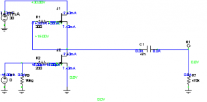
I would like introduce more simply project, such a simply design is almost distortionless with low level signals, low order distortions starts with higher levels.
Every circuit like this should be supplied with separate power port (stabiliser).
In my guitar amp I use this circuit like a single tube with very good results (with cheap BF245 types). Other fets might have too much gain. Fets should have identical Idss.
Of course it eats much more current!
200mV AC at the input, gain X10.
Attachments
padamiecki said:You may try Aikido wersion!
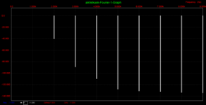
sorry for the graphics
and fft 200mV at the input, over 2 volts ac at the output,
graphics is awful, 2nd harm is -49dB, 3nd - 90db, rest up to - 140dB.
Attachments
G.Kleinschmidt said:Hey, are you getting your cheap SST404's in low quantities? I've downloaded the Vishay datasheet for these and I reckon they would be nice for the discrete differential preamp stage I'm planing to build for my current power amp project.
I buy mine from Mouser . They do them for US$3.53 for low quantities. My "dollar or two" guess wasn't terribly accurate.
I used a pair in my power amp (a redesign of David Tilbrook's AEM6000) with DC coupled feedback, and was very impressed. They are well matched, and are nice and quiet. I'm also using a further pair in a smaller 40W version of the same amp (using one pair of output FETs, and running the intermediate stages at lower current with MMBTA06/56s rather than MJE340/350s). This amp is destined for my study, and will be used for my guitar. I'm buying a Line 6 pod DSP amp modeller to act as a preamp so that I can get all the valve distortion, without the valves, and are using a stereo pair of nice flat studio monitors rather than a guitar speaker.
Not a valve in sight. I'm sure Wavebourn would be aghast 🙂
Cheers,
Suzy
suzyj said:
I'm buying a Line 6 pod DSP amp modeller to act as a preamp so that I can get all the valve distortion, without the valves,
Not a valve in sight.
Imitation is the sincerest form of flattery. 😉
runebivrin said:Q5 and Q6 are the same type of transistor.
Since Q6 B-E is connected in parallel with Q5 B-E + Re,
I don't see how the current through either is particularly well defined. If I were to venture a guess, I'd say Q5 can be removed without any adverse effects.
Am I missing something?
Rune
🙂
Hej Rune
jomenvisst är du missandes something
An externally hosted image should be here but it was not working when we last tested it.
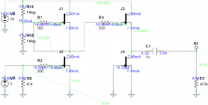
If you look at this schematic, input JFET pair, is taking theortically 50% of CCS - constant current source = Q1.
At positive signal:
The left input FET provides, puts more current into Q6 base.
No problem see this.
The right input FET, using a very precise! Current Mirror, Q4-Q5 + two 10 k resistors
at positive signal
reduces Q6 base current, with same amount.
This makes Current Mirror make use of BOTH Input Pair gains! Their work.
Theoretically, each JFET will only do half the job,
than without mirror.
---------------------------------------------------------------
This is a very good thing, as like
when I go from home I walk very nice and easy
but on my way home,
AFTER BUYTING 15 KG POTATIS OCH KÖTTBULLAR for my food supply,
Carrying all this weight,
I no longer will walk as nice and easy.
Same with transistors
- less work = nice and fast and linear and easy, hopefully
- more or too much work - less nice and easy.
=============================================
Say at some positive signal, LEFT FET takes 52% of Q1 delivered constant current.
This means 48% will run in other FET.
But at Q6 base ...... will be 52%-48% = 4% increase!
While in a case where we would not use one mirror,
as would also work - and is also many times used - and what you are very right about.
In this case the increase at Q6 base would be only 52%-50% = 2%.
Or if feedback tells we need one 4% increase at Q6 base
this would mean
Input pair would HAVE TO share current like: 54%-46%.
Instead of 'HALF THE JOB': 52%-48%
I think you get it, Rune
Regards
västerbottningen
lineup 🙂
suzyj said:
The simplest ones are buffers (eg http://www.diyaudio.com/forums/showthread.php?postid=1075612#post1075612).
The one I'm building (http://www.diyaudio.com/forums/showthread.php?postid=1077620#post1077620 ) has 10dB gain as presented, but of course can be pretty much anything.
The input impedence of your amp or effect box is high impedance (it has to be). However the output of a normal pickup is also very high impedance (to get as much voltage as possible without taking excessive energy from the string and damping it).
What this means is that parasitic capacitance (for example by using a long lead between the guitar and amp) reduces the high frequencies, and changes the tone of the guitar.
If you put a buffer at the pickup, you both minimise stray noise and RFI picked up on the cable, and also ensure that the signal at the pickups makes it through to the other end without the high frequencies being clobbered.
That's without gain. With gain, you can improve the S/N ratio, and if you use a pickup with fewer turns, you can get better sustain.
Cheers,
Suzy
Nice work! It is refreshing to see a clean logical approach to design.
I have been looking into pickups for some time, and it seems to be all about voltage for the guys going for distortion. I believe that the standard Strat pickup is 8,000 turns, and the hot overwound versions about 10,000. That's got to have some inductance and I agree that the cable loading is going to form a filter with that source impedance.
It's seems that a basic model would be a voltage source, series R due to the fine wire and series L due to the inductance. I've not gotten around to simulating this.
I sure would not want to wind or rewind 8 to 10K turns for a rewind so some gain in the amp will help in this respect.
I'm not sure about your theory of the pickup loading and damping the string, as one has to ask if the losses are significant compared to the string, and body? I doubt it, as I believe that the hot pickups have better sustain.
The windings on the Strat pickups are oval covering all the pole magnets and I have to wonder how efficient this could be as it would seem that much of the wire is wasted with no string or magnet to induce voltage. Seems it would make sense to wind each of the round magnets individually, also lends itself to using a drill. Duncan does make rail pickups where the magnet is a long plate and might provide better (more linear) output with large string excursion.
Interesting thread!
Pete B.
Strangely, I woke up tonight thinkning: "Doh". The schematic jumped to me and screamed: "The base is connected to the collector, stupid!"lineup said:
🙂
Hej Rune
jomenvisst är du missandes something
Regards
västerbottningen
lineup 🙂
I must have been really tired when I looked at it last time.
Rune
(som inte är från Västerbotten, men gjorde lumpen i Östersund och repmånader mellan Boden och Kiruna)
runebivrin said:
Strangely, I woke up tonight thinkning: "Doh". The schematic jumped to me and screamed: "The base is connected to the collector, stupid!"
I must have been really tired when I looked at it last time.
Rune
(som inte är från Västerbotten, men gjorde lumpen i Östersund och repmånader mellan Boden och Kiruna)
Rune,
yeah, I wouldn't have need to explain this to you.
I suspected maybe you had the knowledge.
But no regrets for writing, once more, one mini-tutorial 😉
There are more silent readers here around!
than we will ever know ....
Nice house ... Stockholm - neighbourhood ??
An externally hosted image should be here but it was not working when we last tested it.
suzyj said:
I buy mine from Mouser . They do them for US$3.53 for low quantities. My "dollar or two" guess wasn't terribly accurate.
I used a pair in my power amp (a redesign of David Tilbrook's AEM6000) with DC coupled feedback, and was very impressed. They are well matched, and are nice and quiet. I'm also using a further pair in a smaller 40W version of the same amp (using one pair of output FETs, and running the intermediate stages at lower current with MMBTA06/56s rather than MJE340/350s). This amp is destined for my study, and will be used for my guitar. I'm buying a Line 6 pod DSP amp modeller to act as a preamp so that I can get all the valve distortion, without the valves, and are using a stereo pair of nice flat studio monitors rather than a guitar speaker.
Not a valve in sight. I'm sure Wavebourn would be aghast 🙂
Cheers,
Suzy
Bugga. The Mouser price looks a bit better, but the freight cost doesn’t. I’ve now simplified my preamp design down to four 404’s per channel. The preamplifier I’m designing is a completely over the top design to go with the completely over the top hybrid 1kW rms class A stereo amplifier I’m currently designing/building for my lounge room (the circuit of which I linked to in a previous post).
I’ve had a read through your power amp page. Nice job! Your comments on keeping the input sensitivity low to take advantage of the preamps output swing has given me a good idea. I’ve decided to do the same thing and whack my power amps sensitivity right back to 5 or 6 Vrms. The lower closed loop gain will improve the power amplifiers phase margin, meaning the loop compensation can be increased in frequency, giving lower high frequency distortion. Lowering the closed loop gain will also increase the ratio of open-to-closed loop gain, thus lowering distortion throughout the entire audio band.
Cheers,
Glen
- Status
- Not open for further replies.
- Home
- Live Sound
- Instruments and Amps
- Discrete guitar preamp