Ray,
Expect? Nice attitude you have there. I have observed it before, and was fully expecting your two-penneth at some point.
Some people come here to learn and research. In fact, I would hope we ALL come here to learn, regardless of experience - I've certainly learnt plenty over the years, and am grateful to the respective posters.
I have also seen some tremendously stupid battles of egos, and have no wish to get involved, though it is an unfortunate matter of habit if provoked. Many is the time I felt the urge to issue a "smackdown" to a particularly offensive sort, but discipline and experience saw me apply a little common sense.
There is no expectation of anyone to "nanny" the so implied "lazy" people, or bully them into submission. It strikes me as a rather sad way to spend time. Have they nothing better to do but prey upon the inexperienced? Or are they compensating for something?
For such people, I would ask this - just think twice before you hit the reply button, eh? I know it takes "precious" time, but you may find other things to do beyond the screen... like DIY audio...
Peace,
Tom.
This is an open forum and if you are not prepared to do the research or even make the slightest effort to learn the subject, as some clearly are not, you should expect to be ridiculed.
Expect? Nice attitude you have there. I have observed it before, and was fully expecting your two-penneth at some point.
Some people come here to learn and research. In fact, I would hope we ALL come here to learn, regardless of experience - I've certainly learnt plenty over the years, and am grateful to the respective posters.
I have also seen some tremendously stupid battles of egos, and have no wish to get involved, though it is an unfortunate matter of habit if provoked. Many is the time I felt the urge to issue a "smackdown" to a particularly offensive sort, but discipline and experience saw me apply a little common sense.
There is no expectation of anyone to "nanny" the so implied "lazy" people, or bully them into submission. It strikes me as a rather sad way to spend time. Have they nothing better to do but prey upon the inexperienced? Or are they compensating for something?
For such people, I would ask this - just think twice before you hit the reply button, eh? I know it takes "precious" time, but you may find other things to do beyond the screen... like DIY audio...
Peace,
Tom.
Noone should expect to be rediculed. This is a friendly forum I want to believe. The ideas prestented here mustn't be rocket science in order to please some....you should expect to be ridiculed.
Let's try and get this back on topic...
Attached is an LTSpice schematic that shows the actual values of the right channel from the matching software before soldering. (Yes, I know they've probably shifted a bit since then, but haven't got around to re-measuring...)
It demonstrates the kind of precision to aim for. These positions are made from relatively humble "0.1%" 0805 resistors, but it just shows what a bit of measurement and software can do, if you have the patience.
People might find it interesting to play with the resistor values in the schematic, and see how the test voltage output is affected (a basic simulation has been set up to turn each bit on in sequence).
One thing I meant to do was write a software program to take the simulated LTSpice output values, and apply those bit weightings to an audio test file, so the theoretical FFT can be compared to the real-life boards playing the same file. This doesn't go into drift, switch Z, IMD, network inductance, or a few other things, but nevertheless would have been interesting.
The more eagle-eyed among you might notice that the R and 2R chains aren't all that close to double each other... this is a matter of prioritisation, as the Rs are the most important, so get first choice of resistors in the matching process. The trim resistors are chosen to compensate for this ratio error as well as the switch Z..
- Tom.
Attachments
tbrowne said:Let's try and get this back on topic...
Hi,
it seems very interesting. Is there a PCB for this dac with resistors. I have found some vhishays 1% for 0.05EUR (I think they are 1206) and it seems calming to trim them in spare time 🙂 At least is there a full shematics for the DAC with SPDIF receifer.
Thanks,
Pred
Did anyone notice the LTSpice file I posted was actually for the old 20-bit version? Ahem... never mind.
Hi Pred,
Well, I have four spare PCBs for Rev.4, and probably enough components (inc. resistors) to populate them. It would be a brave person who takes it on, but they need to get their interface sorted out first.
Trying to put 1206s onto the 0805 pads of my boards would be less calming, I suspect. Do feel free to design your own, though.
I'd spend a little more on resistors, and go with 0.1% parts, as this means you have to reject less. After considerable research, I went with the Susumus at Digikey (or Rhopoint, for those in the UK). The price is extremely good, and the datasheet is more revealing than most.
The only likely thing better is bulk foils.
I don't use S/PDIF... if anyone wants to castrate the performance by doing that, it's their choice. My experience has been that every DAC I've run over direct I2S sounds better that way... significantly better... unless you slave the transport, which usually involves modifying it.
The Discrete DAC also needs a digital filter... it will produce *sound* running non-oversampling, of course... just nothing too pleasant... at least to these ears. This is handled by the Ti48 transport in my case, though a DF1704/6 is also likely to do a decent job (a few PCM1704 designs are likely to include schematics close to what you need).
By far the easiest way for someone to implement the Discrete DAC is to use a CD player which already has dual mono DACs and a digital filter chip. Even better, something that used old unipolar DAC (PCM58?), so you don't even need to flip the MSB.
Not that the word justification would be the same - the old stuff seems to be mostly left justified format rather than I2S, so my own PCBs would need substantial modification without adjusting the stream, otherwise the MSB would be lopped off... fun, isn't it? 😉
If people have a player, and all the information on the DAC section, I can probably give advice on how hard it would be to connect up the Discretes.
Alternatively...
For the sake of simplicity (although that depends on your POV), I would recommend using a PC-based system with an I2S-using soundcard... you'll need something with more than stereo capability that can handle rates up to at least 24-bit 96kHz. 192kHz may have a small benefit if not outweighed by jitter. Something like an M-Audio Revolution, perhaps.
It was my intention to modify the Foobar2000 ASIO driver to output in a suitable format to feed directly into the Discrete PCBs, giving the opportunity to output from a wide range of sources, but have been unable to get the blessed thing to compile! 😡
Failing that, I could add support to my own Win32 software to support Discrete output, if there's actually someone out there willing to try.
I've had some fast convolution software (along the lines of BruteFIR) for a while that has never seen the light of day... this would be an ideal candidate, I suspect.
- Tom.
Hi Pred,
Is there a PCB for this dac with resistors
Well, I have four spare PCBs for Rev.4, and probably enough components (inc. resistors) to populate them. It would be a brave person who takes it on, but they need to get their interface sorted out first.
I have found some vhishays 1% for 0.05EUR (I think they are 1206) and it seems calming to trim them in spare time 🙂
Trying to put 1206s onto the 0805 pads of my boards would be less calming, I suspect. Do feel free to design your own, though.
I'd spend a little more on resistors, and go with 0.1% parts, as this means you have to reject less. After considerable research, I went with the Susumus at Digikey (or Rhopoint, for those in the UK). The price is extremely good, and the datasheet is more revealing than most.
The only likely thing better is bulk foils.
At least is there a full shematics for the DAC with SPDIF receifer.
I don't use S/PDIF... if anyone wants to castrate the performance by doing that, it's their choice. My experience has been that every DAC I've run over direct I2S sounds better that way... significantly better... unless you slave the transport, which usually involves modifying it.
The Discrete DAC also needs a digital filter... it will produce *sound* running non-oversampling, of course... just nothing too pleasant... at least to these ears. This is handled by the Ti48 transport in my case, though a DF1704/6 is also likely to do a decent job (a few PCM1704 designs are likely to include schematics close to what you need).
By far the easiest way for someone to implement the Discrete DAC is to use a CD player which already has dual mono DACs and a digital filter chip. Even better, something that used old unipolar DAC (PCM58?), so you don't even need to flip the MSB.
Not that the word justification would be the same - the old stuff seems to be mostly left justified format rather than I2S, so my own PCBs would need substantial modification without adjusting the stream, otherwise the MSB would be lopped off... fun, isn't it? 😉
If people have a player, and all the information on the DAC section, I can probably give advice on how hard it would be to connect up the Discretes.
Alternatively...
For the sake of simplicity (although that depends on your POV), I would recommend using a PC-based system with an I2S-using soundcard... you'll need something with more than stereo capability that can handle rates up to at least 24-bit 96kHz. 192kHz may have a small benefit if not outweighed by jitter. Something like an M-Audio Revolution, perhaps.
It was my intention to modify the Foobar2000 ASIO driver to output in a suitable format to feed directly into the Discrete PCBs, giving the opportunity to output from a wide range of sources, but have been unable to get the blessed thing to compile! 😡
Failing that, I could add support to my own Win32 software to support Discrete output, if there's actually someone out there willing to try.
I've had some fast convolution software (along the lines of BruteFIR) for a while that has never seen the light of day... this would be an ideal candidate, I suspect.
- Tom.
Well, I have four spare PCBs for Rev.4, and probably enough components (inc. resistors) to populate them. It would be a brave person who takes it on, but they need to get their interface sorted out first.
I am using a DVD player at the moment and thake the SPDIF for my present dac (convertus clone). My opininon is that SPDIF although inferior could give a momentum to your project.
My intention was to stock some project for future. Sorting resistors seemd like fun and more okward in my vifes eyes 🙂 She still does not understand why a two Jensen or AN capacitors seem like a nice xmas present 🙂
To be brief I am not that motivated to pull the project and participate. As for resistances in farnell catalogues the difference between 1% and 0.1% resistors is 15 times! So I thought to take the cheaper version and like multiply the number of necessary resistors by 5 and hope to get good resistors. BTW did you find some easy way of measuring SMD resistors, I asume that even the grease from the hands can introduce some errors?
The other reason for interest in your project is that I had an idea of making my own sigma delta dac for which 8-10 bit flash dac would be perfect. If someone whants to know why and how much - just for the hack of it and much more than PCM1792.
Sorry for introduction of a little bit of noise and nonlinearity 😉 in your thread,
Pred
Konnichiwa,
Hmmm, I have so far not gotten LT Spice, still using P-Spice....
Hmmm, I'm brave (and experienced enough) with SMD to do it.
Will I2S do the trick?
I have that in my DVDP (it also happens to have an LC Audio Zap Filter.....
Sayonara
tbrowne said:Did anyone notice the LTSpice file I posted was actually for the old 20-bit version? Ahem... never mind.
Hmmm, I have so far not gotten LT Spice, still using P-Spice....
tbrowne said:Well, I have four spare PCBs for Rev.4, and probably enough components (inc. resistors) to populate them. It would be a brave person who takes it on, but they need to get their interface sorted out first.
Hmmm, I'm brave (and experienced enough) with SMD to do it.
Will I2S do the trick?
I have that in my DVDP (it also happens to have an LC Audio Zap Filter.....
Sayonara
am using a DVD player at the moment and thake the SPDIF for my present dac (convertus clone). My opininon is that SPDIF although inferior could give a momentum to your project.
I don't doubt it, but that would be missing the point of the project, IMO. Yes, momentum is nice, but sound quality is nicer.
Making S/PDIF sound good without a clock link is not straightforward... it's not impossible, I know. But why bother? I guess it depends what is more important to you, doesn't it... convenience or quality.
It would be a technical challenge, but very much akin into going to battle with one hand tied behind your back... that usually takes incentive.
As I said, I didn't expect anyone to take up the challenge to build one - mainly because of the lack of S/PDIF interface. It was more out of hope than anything else that someone was "hardcore" rather than pipe and slippers...
(Heh... that word conjures up an audio memory of Pulp's "This Is Hardcore"... with that sleazy brass introduction... shame I don't have it in my music collection.. funny how words can trigger musical memories...)
To be brief I am not that motivated to pull the project and participate. As for resistances in farnell catalogues the difference between 1% and 0.1% resistors is 15 times!
Careful research is required. I've already saved people the effort by saying what resistors I decided on.
I would note that, yes, you can get SMD resistors for a fraction of a penny each on a reel, but in that case it seems you get what you pay for... a quality resistor generally has much tighter tolerances than what the datasheet specifies.
BTW did you find some easy way of measuring SMD resistors, I asume that even the grease from the hands can introduce some errors?
SMD probe tweezers for measuring. Inverted tweezers for placement. They should never need to be touched by hand.
The other reason for interest in your project is that I had an idea of making my own sigma delta dac for which 8-10 bit flash dac would be perfect.
Maybe, maybe not. Depends how good the resistor matching is. You can't tell with 8-10 bit conventional input. The nasty surprise will come when you run the noise shaped audio data through...
Sorry for introduction of a little bit of noise and nonlinearity 😉 in your thread
No problem. It still sounds good from here... 😉
- Tom.
Hi KYW,
It's a free download... here...
http://ltspice.linear.com/software/swcadiii.exe
🙂
For the sake of some more sonic feedback, a kit of parts for Rev.4 boards can be offered "at cost" to people prepared to deal with the interfacing issue. But only for the remaining TWO stereo pairs.
And I'm only going to sell to people who are deadly serious about getting it working (sorry, but I have to be elitist here). I've spent too much time on this project for them to just sit on someone else's bench... after all, I still have use for them myself, experimenting with different impedance ladders and logic families.
People who intend to use the boards with oversampling and separate channel data lines will get "first pick", as that makes the most meaningful comparison to what I'm experiencing here.
It's unlikely I'm going to have any more Rev.4 boards made, and I can't honestly say whether there will be a further revision. That depends on things outside this project... mostly whether I'm earning a living or not.
Audio has been rather more than a hobby to me for the past few years, but my approach seems to lack the compromises necessary to succeed in the "big bad world"...
The short answer is "maybe". The long answer...
I know you're of the NOS persuasion, so the lack of digital filter isn't a direct problem (I think I've made my own feelings clear on NOS already, and you do have the experience to try and ameliorate the gross IMD that can result, if you so wish). The issues are flipping the MSB, and working with stereo interleaved I2S instead of separate as-mono lines per channel.
They all kind of go hand in hand, as you'd need to reconfigure a substantial part of the board in my particular design (may be cleaner to do your own PCB - actually, just using veroboard worked surprisingly well).
Firstly, one '86 gate can be used for the bipolar to unipolar conversion after parallel output. No real problem here. The induced jitter is barely worth worrying about, IMO, as the MSB doesn't switch that often.
Secondly, you don't want to double the wordlclock. Instead (and I haven't tested this) feed the wordclock straight through to one boards' '595s, and on the other board, use an '86 gate to invert it, to decode the other channel.
If I've got it correct (and I might not), the other channel we're not interested in will simply fall off the edge of the '595 shifter chain.
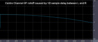
This leaves you with the third problem. The interleaved streams results in a one sample shift between left and right channels. If you were oversampling, this wouldn't be a problem (as it stands, 24/96 DAD discs will probably be fine), but on CDs played at straight 44.1, this is going to give a big phase shift in the centre stage.
As a result, I'd expect vocals to be a bit rolled off, pulling them behind the speakers rather than projecting forward. But I've never tried this interleaved arrangement, so it might be much more subtle than I'm making out.
AFAIK, some old DACs also suffered from this problem, as they used a single converter to reproduce both channels (cost saving measure?).
Anyway, two separate data streams is definitely preferable.
Yes, I know. 😉
It's highly unlikely you'll be able to get acceptable performance using the Zap Filter together with the Discrete and NOS, unless it is very, VERY wide bandwidth.
Hard enough at 4X oversampling. I've tried PNP and FET buffers, and it just completely spoilt the sound. The best output stage found so far is simply a 220pF cap to ground, and a 47uF coupling cap.
- Tom.
Hmmm, I have so far not gotten LT Spice, still using P-Spice....
It's a free download... here...
http://ltspice.linear.com/software/swcadiii.exe
Hmmm, I'm brave (and experienced enough) with SMD to do it.
🙂
For the sake of some more sonic feedback, a kit of parts for Rev.4 boards can be offered "at cost" to people prepared to deal with the interfacing issue. But only for the remaining TWO stereo pairs.
And I'm only going to sell to people who are deadly serious about getting it working (sorry, but I have to be elitist here). I've spent too much time on this project for them to just sit on someone else's bench... after all, I still have use for them myself, experimenting with different impedance ladders and logic families.
People who intend to use the boards with oversampling and separate channel data lines will get "first pick", as that makes the most meaningful comparison to what I'm experiencing here.
It's unlikely I'm going to have any more Rev.4 boards made, and I can't honestly say whether there will be a further revision. That depends on things outside this project... mostly whether I'm earning a living or not.
Audio has been rather more than a hobby to me for the past few years, but my approach seems to lack the compromises necessary to succeed in the "big bad world"...
Will I2S do the trick?
The short answer is "maybe". The long answer...
I know you're of the NOS persuasion, so the lack of digital filter isn't a direct problem (I think I've made my own feelings clear on NOS already, and you do have the experience to try and ameliorate the gross IMD that can result, if you so wish). The issues are flipping the MSB, and working with stereo interleaved I2S instead of separate as-mono lines per channel.
They all kind of go hand in hand, as you'd need to reconfigure a substantial part of the board in my particular design (may be cleaner to do your own PCB - actually, just using veroboard worked surprisingly well).
Firstly, one '86 gate can be used for the bipolar to unipolar conversion after parallel output. No real problem here. The induced jitter is barely worth worrying about, IMO, as the MSB doesn't switch that often.
Secondly, you don't want to double the wordlclock. Instead (and I haven't tested this) feed the wordclock straight through to one boards' '595s, and on the other board, use an '86 gate to invert it, to decode the other channel.
If I've got it correct (and I might not), the other channel we're not interested in will simply fall off the edge of the '595 shifter chain.
This leaves you with the third problem. The interleaved streams results in a one sample shift between left and right channels. If you were oversampling, this wouldn't be a problem (as it stands, 24/96 DAD discs will probably be fine), but on CDs played at straight 44.1, this is going to give a big phase shift in the centre stage.
As a result, I'd expect vocals to be a bit rolled off, pulling them behind the speakers rather than projecting forward. But I've never tried this interleaved arrangement, so it might be much more subtle than I'm making out.
AFAIK, some old DACs also suffered from this problem, as they used a single converter to reproduce both channels (cost saving measure?).
Anyway, two separate data streams is definitely preferable.
I have that in my DVDP (it also happens to have an LC Audio Zap Filter.....
Yes, I know. 😉
It's highly unlikely you'll be able to get acceptable performance using the Zap Filter together with the Discrete and NOS, unless it is very, VERY wide bandwidth.
Hard enough at 4X oversampling. I've tried PNP and FET buffers, and it just completely spoilt the sound. The best output stage found so far is simply a 220pF cap to ground, and a 47uF coupling cap.
- Tom.
Hi Tom,
That's a very generous offer.
I think I may have to pass as the idea in my head differs enough that, as you say ... "as you'd need to reconfigure a substantial part of the board in my particular design "
I'd be happy to share feedback with you once I get something made.
...and finally, an apology:
I 'sort of' prompted this thread by asking you for some further details of your descrete-dac, so I feel at least partially responsible for the ****-storm that appears to have landed on you over the weekend from those with closed minds.
My apologies - and best of luck with your VERY interesting project.
Jim.
For the sake of some more sonic feedback, a kit of parts for Rev.4 boards can be offered "at cost" to people prepared to deal with the interfacing issue. But only for the remaining TWO stereo pairs.
That's a very generous offer.
I think I may have to pass as the idea in my head differs enough that, as you say ... "as you'd need to reconfigure a substantial part of the board in my particular design "
I'd be happy to share feedback with you once I get something made.
...and finally, an apology:
I 'sort of' prompted this thread by asking you for some further details of your descrete-dac, so I feel at least partially responsible for the ****-storm that appears to have landed on you over the weekend from those with closed minds.
My apologies - and best of luck with your VERY interesting project.
Jim.
Hi Jim,
Thankyou. I've also offered loan of actual completed boards out to a few people, as I don't use the Matrix board version anymore, really. Again, no takers.
It is disappointing to think that people see the interface as such a major stumbling block. It's only logic. If I could justify it, I might be be willing to consider doing a "partial" solution (as in a filter chip plus logic to accept normal I2S), but I'm quite happy with my setup.
I do fully recognise no-one is going to go and buy a Ti48 for an unproven project (least of all when it's already got a very nice partner, IMO), but nevertheless thought some brave soul might have an old player that already uses dual mono streams into separate DACs.
I should also point out that the digital filter *is* important to the sound. Not just any old filter will do. Personally, I prefer a fairly gentle slope for most music, but tastes may differ.
And I'd be more than happy (as would many, I reckon) to hear how you get on!
Have you decided on what route you're going to take with impedance? Switches? Unipolar or bipolar? Filtering?
These all require some thought (and ideally experimentation)... if you have the energy, best to try everything, I guess. 🙂
Naah... don't be daft, I fully expected it. I've been reading these forums for some years, and you do get a small insight into the characters of the posters.
Thanks... I don't think I will be doing anything significant to it in the near future...
Other people now should have a grasp of the work involved from an actual builder, and it is up to them whether they choose to have a go, or stick to their all-in-one lumps...
- Tom.
That's a very generous offer.
Thankyou. I've also offered loan of actual completed boards out to a few people, as I don't use the Matrix board version anymore, really. Again, no takers.
It is disappointing to think that people see the interface as such a major stumbling block. It's only logic. If I could justify it, I might be be willing to consider doing a "partial" solution (as in a filter chip plus logic to accept normal I2S), but I'm quite happy with my setup.
I do fully recognise no-one is going to go and buy a Ti48 for an unproven project (least of all when it's already got a very nice partner, IMO), but nevertheless thought some brave soul might have an old player that already uses dual mono streams into separate DACs.
I should also point out that the digital filter *is* important to the sound. Not just any old filter will do. Personally, I prefer a fairly gentle slope for most music, but tastes may differ.
I'd be happy to share feedback with you once I get something made.
And I'd be more than happy (as would many, I reckon) to hear how you get on!
Have you decided on what route you're going to take with impedance? Switches? Unipolar or bipolar? Filtering?
These all require some thought (and ideally experimentation)... if you have the energy, best to try everything, I guess. 🙂
I 'sort of' prompted this thread by asking you for some further details of your descrete-dac, so I feel at least partially responsible for the ****-storm that appears to have landed on you over the weekend from those with closed minds.
Naah... don't be daft, I fully expected it. I've been reading these forums for some years, and you do get a small insight into the characters of the posters.
best of luck with your VERY interesting project.
Thanks... I don't think I will be doing anything significant to it in the near future...
Other people now should have a grasp of the work involved from an actual builder, and it is up to them whether they choose to have a go, or stick to their all-in-one lumps...
- Tom.
Tom,
Would one of the older Philips players be of any use, particularly one of the Dual 1540 machines.
They only used 14 bits though but im not sure whether this was that the dac just dropped the lsb's or that it didnt even make it as far as them.
😕
Very interesting read,
Brian
Would one of the older Philips players be of any use, particularly one of the Dual 1540 machines.
They only used 14 bits though but im not sure whether this was that the dac just dropped the lsb's or that it didnt even make it as far as them.
😕
Very interesting read,
Brian
Konnichiwa,
Yeah, I know, but I recently tried simming something and could not get anywhere I wanted to, so I gave up for the time being and stuck to what I know.... ;-)
I would definitly want it to work.... ;-)
You know I have ulterior motives.
I don't find "gross IMD". All depends on the analogue circuitry in tow.
I guess I'll manage that... ;-)
All true. But a vero board build will take more time than stuffing even an SMD board....
Actually, 1/2 sample. This has been discussed exhaustively elsewhere, i don't have a problem with this....
It is a very fast pure open loop design. Not bad at all, if you ask me....
Sayonara
tbrowne said:
Yeah, I know, but I recently tried simming something and could not get anywhere I wanted to, so I gave up for the time being and stuck to what I know.... ;-)
tbrowne said:And I'm only going to sell to people who are deadly serious about getting it working (sorry, but I have to be elitist here).
I would definitly want it to work.... ;-)
You know I have ulterior motives.
tbrowne said:I know you're of the NOS persuasion, so the lack of digital filter isn't a direct problem (I think I've made my own feelings clear on NOS already, and you do have the experience to try and ameliorate the gross IMD that can result, if you so wish).
I don't find "gross IMD". All depends on the analogue circuitry in tow.
tbrowne said:The issues are flipping the MSB, and working with stereo interleaved I2S instead of separate as-mono lines per channel.
I guess I'll manage that... ;-)
tbrowne said:They all kind of go hand in hand, as you'd need to reconfigure a substantial part of the board in my particular design (may be cleaner to do your own PCB - actually, just using veroboard worked surprisingly well).
All true. But a vero board build will take more time than stuffing even an SMD board....
tbrowne said:This leaves you with the third problem. The interleaved streams results in a one sample shift between left and right channels.
Actually, 1/2 sample. This has been discussed exhaustively elsewhere, i don't have a problem with this....
tbrowne said:It's highly unlikely you'll be able to get acceptable performance using the Zap Filter together with the Discrete and NOS, unless it is very, VERY wide bandwidth.
It is a very fast pure open loop design. Not bad at all, if you ask me....
Sayonara
Hi Brian,
Probably. I've been spending some time looking at what appears to be a truncated 1540 datasheet... either that, or it just isn't very informative. So please bear with me...
The '595 chain needs to be shortened to two... so the DATA signal would go in at the third '595 rather than the one at the top, and chain broken between 2 and 3. No problem.
You wouldn't need the '86 chip at all, it seems - PROVIDING the data is unipolar/unsigned and not twos' complement (datasheet does not confirm)... don't put it on the PCB and just wire pin 1 to pin 8.
Where the MSB ends up at depends on whether the data is packed 14-bit, or padded to 16-bit.
If it's packed 14-bit, the MSB will appear at QF of the final chip in the chain... this is one bit earlier than usual for the PCB, but there's nothing to stop you from wiring it to the output, and not populating the normal MSB 2R.
If OTOH, it's padded 16-bit, the MSB wil appear at QH. On the PCB, QH is not connected to anything for I2S purposes (this is the empty cycle I've talked about before), but it's pretty trivial to extend the network by one bit, hooking into this output, and moving the output point.
We're only talking about four patch wires and a similar number of trace cuts, AFAIK. Someone else please speak up if there's a flaw in my mods.
14 bits is just fine... providing the digital filter chip goes to at least 4X oversampling and dithers. I would imagine it does.
I think it would certainly be very interesting to try out Discrete modules in such a player. Anyone up for it?
KYW,
[LTSpice]
Tsk, tsk... you haven't changed... 🙂
... 😉
Indeed - I have been giving some thought to our conversation, and I'm not sure what I can offer you.
You need to understand that this project is an unknown quantity to the open-minded members of the group... if you were to come back and say "it's crap" after using it in an entirely different way to what was originally intended (which is what you would be doing), I'm liable to get angry and tell you to "use the b****y thing properly", after the amount of time and effort (and indeed money) I've put into it. I'd wager you've probably said the same thing yourself to others once or twice.
Looks like a no-win situation from my POV... you get to either knock the design or use it to push your own ideas... rather than mine... no fair...
But let's see if anyone else steps up...
Indeed... I presume your signal ends up at a transducer at some point... 😉
Oops, yes... I'm too used to working with separate streams.
I must have missed those threads.
It's not too dramatic on its own (for those who might not know, see the attached graph), but you would compensate for NOS roll-off, right? Otherwise I'd imagine the centre stage would end up at total something like -3dB at 15kHz... or worse... though most speakers (and listeners' heads!) aren't phase matched to that kind of precision, so perhaps it's a storm in a teacup.
I'm sure it will give it "character", though... not that it needs much more!
- Tom.
Would one of the older Philips players be of any use, particularly one of the Dual 1540 machines.
Probably. I've been spending some time looking at what appears to be a truncated 1540 datasheet... either that, or it just isn't very informative. So please bear with me...
The '595 chain needs to be shortened to two... so the DATA signal would go in at the third '595 rather than the one at the top, and chain broken between 2 and 3. No problem.
You wouldn't need the '86 chip at all, it seems - PROVIDING the data is unipolar/unsigned and not twos' complement (datasheet does not confirm)... don't put it on the PCB and just wire pin 1 to pin 8.
Where the MSB ends up at depends on whether the data is packed 14-bit, or padded to 16-bit.
If it's packed 14-bit, the MSB will appear at QF of the final chip in the chain... this is one bit earlier than usual for the PCB, but there's nothing to stop you from wiring it to the output, and not populating the normal MSB 2R.
If OTOH, it's padded 16-bit, the MSB wil appear at QH. On the PCB, QH is not connected to anything for I2S purposes (this is the empty cycle I've talked about before), but it's pretty trivial to extend the network by one bit, hooking into this output, and moving the output point.
We're only talking about four patch wires and a similar number of trace cuts, AFAIK. Someone else please speak up if there's a flaw in my mods.
14 bits is just fine... providing the digital filter chip goes to at least 4X oversampling and dithers. I would imagine it does.
I think it would certainly be very interesting to try out Discrete modules in such a player. Anyone up for it?
KYW,
[LTSpice]
Yeah, I know, but I recently tried simming something and could not get anywhere I wanted to, so I gave up for the time being and stuck to what I know.... ;-)
Tsk, tsk... you haven't changed... 🙂
... 😉
I would definitly want it to work.... ;-)
You know I have ulterior motives.
Indeed - I have been giving some thought to our conversation, and I'm not sure what I can offer you.
You need to understand that this project is an unknown quantity to the open-minded members of the group... if you were to come back and say "it's crap" after using it in an entirely different way to what was originally intended (which is what you would be doing), I'm liable to get angry and tell you to "use the b****y thing properly", after the amount of time and effort (and indeed money) I've put into it. I'd wager you've probably said the same thing yourself to others once or twice.
Looks like a no-win situation from my POV... you get to either knock the design or use it to push your own ideas... rather than mine... no fair...
But let's see if anyone else steps up...
I don't find "gross IMD". All depends on the analogue circuitry in tow.
Indeed... I presume your signal ends up at a transducer at some point... 😉
Actually, 1/2 sample.
Oops, yes... I'm too used to working with separate streams.
This has been discussed exhaustively elsewhere, i don't have a problem with this....
I must have missed those threads.
It's not too dramatic on its own (for those who might not know, see the attached graph), but you would compensate for NOS roll-off, right? Otherwise I'd imagine the centre stage would end up at total something like -3dB at 15kHz... or worse... though most speakers (and listeners' heads!) aren't phase matched to that kind of precision, so perhaps it's a storm in a teacup.
I'm sure it will give it "character", though... not that it needs much more!
- Tom.
Attachments
Konnichiwa,
Well, I'll give you another ring. I might just be happy to use what is there, if it sounds good enough, might pay back some of your investment in time....
Well, IF I really thought in my own application the results where bad (say sub TDA1543?) sonically, I would tell you and I would tell the group members not to use it like that, but given that you already warned "it does not do well like that", so I could not call it any 4 letter words.
If I where to "push" it, chances are I'd be putting bread on your table, which cannot be bad, no matter what sort of ideas I have.
But I'm happy for others to have a go if any fancy soldring a lot of SMD stuff.
Come on, we have been around all of this ages ago on the LLDIYHC list with CF, not again, so, you don't like non-os, cool with me, I do....
Well, the plot would surely be the same if you had a difference in distance to the speakers of around 4mm. Which takes some seriously tight positioning of the head and never mind all the comb filtering etc....
As for the sin(X)/X rolloff, yes, I compensate it....
Sayonara
tbrowne said:Indeed - I have been giving some thought to our conversation, and I'm not sure what I can offer you.
Well, I'll give you another ring. I might just be happy to use what is there, if it sounds good enough, might pay back some of your investment in time....
tbrowne said:You need to understand that this project is an unknown quantity to the open-minded members of the group... if you were to come back and say "it's crap" after using it in an entirely different way to what was originally intended (which is what you would be doing), I'm liable to get angry and tell you to "use the b****y thing properly", after the amount of time and effort (and indeed money) I've put into it. I'd wager you've probably said the same thing yourself to others once or twice.
Well, IF I really thought in my own application the results where bad (say sub TDA1543?) sonically, I would tell you and I would tell the group members not to use it like that, but given that you already warned "it does not do well like that", so I could not call it any 4 letter words.
tbrowne said:Looks like a no-win situation from my POV... you get to either knock the design or use it to push your own ideas... rather than mine... no fair...
If I where to "push" it, chances are I'd be putting bread on your table, which cannot be bad, no matter what sort of ideas I have.
But I'm happy for others to have a go if any fancy soldring a lot of SMD stuff.
tbrowne said:Indeed... I presume your signal ends up at a transducer at some point... 😉
Come on, we have been around all of this ages ago on the LLDIYHC list with CF, not again, so, you don't like non-os, cool with me, I do....
tbrowne said:It's not too dramatic on its own (for those who might not know, see the attached graph), but you would compensate for NOS roll-off, right? Otherwise I'd imagine the centre stage would end up at total something like -3dB at 15kHz... or worse... though most speakers (and listeners' heads!) aren't phase matched to that kind of precision, so perhaps it's a storm in a teacup.
Well, the plot would surely be the same if you had a difference in distance to the speakers of around 4mm. Which takes some seriously tight positioning of the head and never mind all the comb filtering etc....
As for the sin(X)/X rolloff, yes, I compensate it....
Sayonara
KYW,
What I'd love most is for people to listen and find it's as good as I think it is... it isn't perfect, I know, but it what I gets "wrong" I don't care much about... if you see what I mean.
The most futile thing in audio, IMO, is trying to create a system that does everything. Yet we can't help ourselves...
Okay, cool. This is my "baby", so I am rather protective of it. Over-protective, perhaps, but there are only four spare PCBs, and they were expensive to get made.
I never did get around to listening to the TDA1543, I'm afraid - not at least knowingly. Couldn't get past the spec... some amusement can be had from that considering what I'm listening to now!
You're right... but there's a voice in the back of my head shouting "unclean! unclean!"...

The soldering is okay. It's the rework that is the nightmare... don't finish a module after hours of work, and then plug it in backwards...
It's a really bad idea. Trust me. Praise be to Chip Quik.
Measuring the resistors is kind of theraputic... when you develop a working rhythm, you can measure and label them quite quickly.
It's not an issue when we're working in isolation, but it makes it hard to work together - it makes me think we are listening for entirely different things. I would genuinely like you to come up with a NOS iteration that sounds at least as good as my own custom oversampled versions do to me - then I wouldn't have to hate the concept so much.
Let me just spend a little time to try and explain what I've heard with NOS, rather than what I measure. What I hear can be equated to a "layer of mud" over the audio. Things sound rather congested... there's no space between instruments, and the crystalline quality of some recordings is lost.
If you can come up with a design not so afflicted, without completely screwing up the phase and frequency response, or changing the rest of my equipment, credit where it is due.
I listen a lot on headphones. 🙂
Good stuff.
After all, if in-band rolloff was actually wanted (a la various products which claim to "correct" a time response problem that IMO isn't really there - at least with a "good" filter), that could be achieved trivially in the digital domain and used in combination with a good quality OS filter placed further out than normal.
- Tom.
Well, I'll give you another ring. I might just be happy to use what is there, if it sounds good enough, might pay back some of your investment in time....
What I'd love most is for people to listen and find it's as good as I think it is... it isn't perfect, I know, but it what I gets "wrong" I don't care much about... if you see what I mean.
The most futile thing in audio, IMO, is trying to create a system that does everything. Yet we can't help ourselves...
Well, IF I really thought in my own application the results where bad (say sub TDA1543?) sonically, I would tell you and I would tell the group members not to use it like that, but given that you already warned "it does not do well like that", so I could not call it any 4 letter words.
Okay, cool. This is my "baby", so I am rather protective of it. Over-protective, perhaps, but there are only four spare PCBs, and they were expensive to get made.
I never did get around to listening to the TDA1543, I'm afraid - not at least knowingly. Couldn't get past the spec... some amusement can be had from that considering what I'm listening to now!
If I where to "push" it, chances are I'd be putting bread on your table, which cannot be bad, no matter what sort of ideas I have.
You're right... but there's a voice in the back of my head shouting "unclean! unclean!"...
But I'm happy for others to have a go if any fancy soldring a lot of SMD stuff.
The soldering is okay. It's the rework that is the nightmare... don't finish a module after hours of work, and then plug it in backwards...
It's a really bad idea. Trust me. Praise be to Chip Quik.
Measuring the resistors is kind of theraputic... when you develop a working rhythm, you can measure and label them quite quickly.
Come on, we have been around all of this ages ago on the LLDIYHC list with CF, not again, so, you don't like non-os, cool with me, I do....
It's not an issue when we're working in isolation, but it makes it hard to work together - it makes me think we are listening for entirely different things. I would genuinely like you to come up with a NOS iteration that sounds at least as good as my own custom oversampled versions do to me - then I wouldn't have to hate the concept so much.
Let me just spend a little time to try and explain what I've heard with NOS, rather than what I measure. What I hear can be equated to a "layer of mud" over the audio. Things sound rather congested... there's no space between instruments, and the crystalline quality of some recordings is lost.
If you can come up with a design not so afflicted, without completely screwing up the phase and frequency response, or changing the rest of my equipment, credit where it is due.
Well, the plot would surely be the same if you had a difference in distance to the speakers of around 4mm. Which takes some seriously tight positioning of the head and never mind all the comb filtering etc....
I listen a lot on headphones. 🙂
As for the sin(X)/X rolloff, yes, I compensate it....
Good stuff.
After all, if in-band rolloff was actually wanted (a la various products which claim to "correct" a time response problem that IMO isn't really there - at least with a "good" filter), that could be achieved trivially in the digital domain and used in combination with a good quality OS filter placed further out than normal.
- Tom.
Konnichiwa,
Hmmm, I certainly do not hear that....
Unless I'm using my portable on the way to/from work I never do.
Like "Legato Link" (except that is more like Non-Os than most people realise)...?
Sayonara
tbrowne said:Let me just spend a little time to try and explain what I've heard with NOS, rather than what I measure. What I hear can be equated to a "layer of mud" over the audio. Things sound rather congested... there's no space between instruments, and the crystalline quality of some recordings is lost.
Hmmm, I certainly do not hear that....
tbrowne said:I listen a lot on headphones. 🙂
Unless I'm using my portable on the way to/from work I never do.
tbrowne said:After all, if in-band rolloff was actually wanted (a la various products which claim to "correct" a time response problem that IMO isn't really there - at least with a "good" filter), that could be achieved trivially in the digital domain and used in combination with a good quality OS filter placed further out than normal.
Like "Legato Link" (except that is more like Non-Os than most people realise)...?
Sayonara
Hmmm, I certainly do not hear that....
Could be disguised... though you may not agree. 😉
I found putting in a second order output filter to be a vast improvement over first order for NOS (no surprise there), but it still wasn't quite right. Have tried steeper, but not as an integral slope (if you see what I mean - perhaps another octave out or so). For all intents and purposes, the filter was *steeper* than the digital equivalent I usually employ, yet it still wasn't doing as good a job.
If I was hearing *anything* I perceived as beneficial over 4xOS, I'd have bothered to pursue it further. So those are my experiences, anyway...
Like "Legato Link" (except that is more like Non-Os than most people realise)...?
I'm not aware of any hard data on how "Legato Link" filters inside the IC - presumably as they don't tend to OEM such parts. All the information and tests I've ever encountered simply points to a gentle, low-tap filter, with some roll-off below 20K... not substantially different to any other player or DAC over the years employing a gentle filter.
In my experience, a gentle digital filter is still a world away from none at all, in both listening and measurements. YMMV. 🙂
- Tom.
I've been looking at invoices today to try and work out how much the Discrete boards actually cost me in terms of parts - I certainly don't have it down to the penny (now you see why I would not make a great accountant).
It's looking like it was around 50 quid for a pair, not including some bits around the edges that I already had (Molex headers, output bits), though that doesn't reflect some overbuying I did to hit price breaks.
For someone like me who doesn't build hardware too quickly, I'd estimate the time to complete two boards from scratch to be around six hours... though it could probably be done in half that time by an experienced SMD worker. That includes measuring the individual resistors, which I estimate approx. an hour if you're doing it to the recommended five digits.
It'd be better if the DIYer didn't want the same Oscons I used, because I've only got three left (grr!). I haven't tried anything else in that location, but feel it is wasted when there are local C0Gs, and also the value isn't really big enough.
I had to bulk up on off-board reservoir for this lower impedance network, as I felt it was running out of steam a little on the really loud bits (the lower Z network is definitely more PSU-sensitive than the old one, IMO)... would recommend trying 470uF instead of 100uF for this revision and network... the pads on the board should accomodate it. Would suggest Panasonic FK as a possible candidate.
In comparison, the Rev.1 on veroboard using 1% resistors, slower HC logic, cost something like 30 quid a pair, and IIRC, the bits of beige-coloured hole-filled material were actually more expensive than the components put on it, IIRC... 🙂
- Tom.
By far the easiest way for someone to implement the Discrete DAC is to use a CD player which already has dual mono DACs and a digital filter chip.
I find this discrete DAC very interesting. I don't have the knowledge to help with the needed logic (I will rather be a follower), but at the first moment it seems that my 'old' Sony CDP227ESD will be a perfect donor for the needed I2S, because it has two TDA1541A (of course feeded through I2S) and I am almost sure it's one per channel (can anyone comment on it?) And probably the digital filter chip is also into there...
If I only had the time... 🙂
Erik
- Status
- Not open for further replies.
- Home
- Source & Line
- Digital Line Level
- Discrete DAC