A modified version of Martin King's MathCAD worksheets, the accuracy of which has been demonstrated for two decades and is sufficiently well-known not to need any further comment on my part.
.......and we've compared enough sims between it an Hornresp
to satisfy me that it's accurate enough, so folks can use its various box type wizards to do their own sims/comparisons to see how high enough aspect ratios affect driver response, vent location.
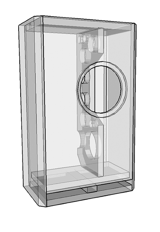
here is a box with one vent at three different locations
This does not prove that one is better than the other, the 3 curves are more alike than different. They are of no consequence once room effects dominate.
This does not prove that one is better than the other, the 3 curves are more alike than different. They are of no consequence once room effects dominate.
i did not say one is better then the other, i only stated that different vent location gives different results, and i showed it too. it is simply incorrect to say that vent location does not matter.
if the effect is minor or not is up to the builder.
They do. With a straight line with no complexity they will occur at the fundemental [F], 3F, 5F, 7F…. dave
Just curious why the 2nd and 4th standing wave modes would not be a problem?
And also whether it would just be true for the special case of a smaller enclosed space like a speaker cabinet or if it would also be true for the standing waves in a room?
To generate even order harmonics i believe one needs a half-wave line. The odd-order generation is due to the nature of a pipe open at one end.
Pipe physics. GM has a link to a good site that covers that. MJK’s papers is also good.
dave
Pipe physics. GM has a link to a good site that covers that. MJK’s papers is also good.
dave
i did not say one is better then the other, i only stated that different vent location gives different results, and i showed it too. it is simply incorrect to say that vent location does not matter.
True. I have found this thread very informative. The vented box models I have always used are based on the assumption that the vented box is an idealized Helmholtz resonator. It is fascinating to see the results of more advanced models and experimental data which backs it up.
All models and simulations are based on simplifying assumptions. As engineers, scientists, and mathematicians, we all must make some simplifying assumptions or we would never get off the starting line.
So it is important to understand what assumptions have been made in the development of a simulation tool. We must always be aware of the limitations.
I now believe that there were good reasons that so many speakers from 40+ years ago were boxes in the form of Depth:Width:Height of approximately 1.0 : 1.6 : 2.6. This shape is seen in many BBC-style speakers, as well as JBL, AR, Advent, etc. Those designers knew the limitations of the many assumptions they were forced to make... including the assumption that the box was an ideal Helmholtz resonator. The did not make tall slim towers as vented boxes because the necessary assumption would fall apart.
What a great discussion!
All models and simulations are based on simplifying assumptions. As engineers, scientists, and mathematicians, we all must make some simplifying assumptions or we would never get off the starting line.
Until the advent of chaos/complexoty theory mathematics generally stuck to the 5% or so of problems that do not involve it.
dave
...from 40+ years ago were boxes in the form of Depth:Width:Height of approximately 1.0 : 1.6 : 2.6...
Note that that approximation is really close to a 1:1.618:1.6182. Golden Ratio again.
This is the same as 0.618:1:1.618 so we have the Classic Golden Ratio box.
So one would expect they are using the same sort of irrational numbers when working the box proportions.
dave
To generate even order harmonics i believe one needs a half-wave line. The odd-order generation is due to the nature of a pipe open at one end.
Pipe physics. GM has a link to a good site that covers that. MJK’s papers is also good.
dave
Thanks Dave
Guess I'm confused because I've found 3 different equations.
Where v = speed of sound
and L = interior length of the cabinet/pipe,
For a pipe open at both ends: F = nv/2L and n = any integer,
for a pipe open at only 1 end: F = nv/4L and n = odd integers,
for a pipe closed at both ends: F = nv/2L and n = any integer.
So I get what you are talking about for a regular TL, but I guess I'm thinking of a ported (and sealed as well?) cabinet as being closed at both ends. Perhaps that is incorrect.
Any box with a hole in it will act (in some ways) like a quarter wave enclosure (the 4), a sealed box would be a half-wave TL (the 2). If there are 2 holes their placement will determine when it becomes a half-wave line. I have seen no experimentation with 2 terminus (mass-loaded or not), i expect there would be a broad range of complex hybrid action between the extremes.
With only odd integers only odd harmonics can form, with any integer we get all the harmonics.
dave
With only odd integers only odd harmonics can form, with any integer we get all the harmonics.
dave
Study musical instrument design for multiple taps and of course the mouthpiece entry is the 'driver' location. 😉
Right then. A ported cabinet acts like a pipe with 1 end open and a driver at the other and so would be considered a quarter wave pipe.
The trouble for me trying to learn this is that I then look a a different real world example and this position doesn't look to be supported:
Internal standing waves - How to eliminate them from loudspeaker boxes
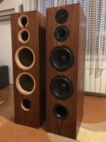
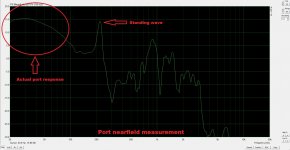
Without reading the whole thing, it's a ported cab with an internal top to bottom dimension of 750mm/29.5" with a port near the bottom, pic 1. Pic 2 is the near field port response. The port is tuned to 25Hz.
If it's acting like a 1/4 wave pipe, then F(1) = 13,377/4*29.5 = 113Hz, F(3) = 339Hz and F(5) = 565Hz.
On the other hand, if it's acting like a 1/2 wave pipe that is closed at both ends, F(1) = 13,377/2*29.5 = 226Hz, F(2) = 452Hz, F(3) = 680Hz and so on.
And clearly the big spike coming out of the port is located at ~220Hz.
Can anybody clear up my confusion?
The trouble for me trying to learn this is that I then look a a different real world example and this position doesn't look to be supported:
Internal standing waves - How to eliminate them from loudspeaker boxes
Without reading the whole thing, it's a ported cab with an internal top to bottom dimension of 750mm/29.5" with a port near the bottom, pic 1. Pic 2 is the near field port response. The port is tuned to 25Hz.
If it's acting like a 1/4 wave pipe, then F(1) = 13,377/4*29.5 = 113Hz, F(3) = 339Hz and F(5) = 565Hz.
On the other hand, if it's acting like a 1/2 wave pipe that is closed at both ends, F(1) = 13,377/2*29.5 = 226Hz, F(2) = 452Hz, F(3) = 680Hz and so on.
And clearly the big spike coming out of the port is located at ~220Hz.
Can anybody clear up my confusion?
Attachments
It is not that simple. A quick bit of estimation here:
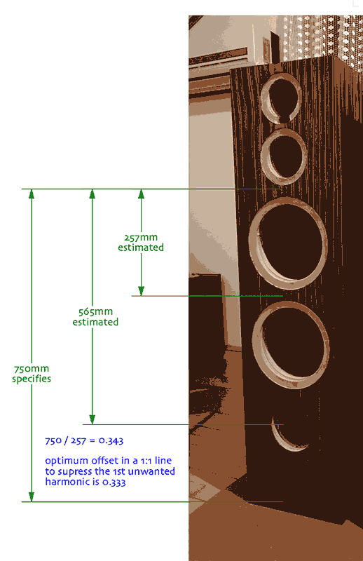
The Zd of this (short) TL is about 0.343. The optimum Zd uses in a 1:1 taper (sttaight) line is 0.333. This offset is used to almost completely supress the 3rd harmonic, leaving the fifth.
Scott or Paul or GM would have to speaker to the other details like Zv that affect the eignmodes.
dave
The Zd of this (short) TL is about 0.343. The optimum Zd uses in a 1:1 taper (sttaight) line is 0.333. This offset is used to almost completely supress the 3rd harmonic, leaving the fifth.
Scott or Paul or GM would have to speaker to the other details like Zv that affect the eignmodes.
dave
Attachments

This does not prove that one is better than the other, the 3 curves are more alike than different. They are of no consequence once room effects dominate.
Yes and no in that the TL modes damp the vent [a lot] more than a simple reflex, so can have greater acoustic efficiency an less internal damping when the driver/vent orientation is optimized. If not, then a secondary set of eigenmodes come into play and can cause a significant notch in the mid-bass when the vent is close to the driver.
Of course one can simply stuff a reflex box and/or its vent to achieve the desired damping, just won't be as efficient and in mine and many folk's experience it's an unacceptable trade-off WRT pace, rhythm & timing [PRaT], ditto when one wants to use [very] low power amps.
FWIW, these are the driver, vent offsets I use/recommend, i.e. at a pipe's odd harmonics: Z = ~ 0.217, 0.349, 0.424, 0.66, 0.714, 0.848
IME, simple fractions are only optimum for open pipe eigenmodes.
More to come as time permits if needed..........
IME, simple fractions are only optimum for open pipe eigenmodes.
More to come as time permits if needed..........
Well, the measurement doesn't support this theory. The max output of the port is at about 25-30Hz. Even with the most optimistic assumption of the effect of tapering (which probably isn't there) and/or effects of acoustic damping (lowering the speed of sound) you won't get that low. Furthermore, the peak at 220Hz proves that, íf there would be a fifth order resonance, the output couldn't peak at 25-30Hz. The peak has a clear cause: the first order resonance is quite severe and the velocity knot at the bottom excites a lot of unwanted sound output through the port (assuming the port itself isn't about 80cm long 😉 ). Just my 2 ct. And the port probably is about 20cm long...This offset is used to almost completely supress the 3rd harmonic, leaving the fifth.
planet10, why suppressing third harmonic would be more important than the first at ~220Hz? With TL it would be since the whole operation is aiming for the resonance, but this is just internal standing wave of a box isn't it? With boxes the lowest modes are the most problematic since damping material inside the box is not so effective as with the higher modes. In this case best place for the woofer (or their acoustic center) would be in the middle if one wanted to kill the lowest ~220hz resonance.
Last edited:
Of course one can simply stuff a reflex box and/or its vent to achieve the desired damping, just won't be as efficient and in mine and many folk's experience it's an unacceptable trade-off WRT pace, rhythm & timing
how do you then deal with internal reflections and cavity resonances which is a plague in it self?
- Home
- Loudspeakers
- Multi-Way
- Disadvantage with putting the port far from the woofer?