I had always read that the port should be as close as possible to the woofer, à la JBL.
However, locating a port very close to the woofer can cause suck outs in the low mid/upper bass, due to reflection from the cone, off the rear baffle, and out of the port.
Certainly, in many cases, midrange leakage via the port is worst when the port is close to the woofer.
I dont think there is a "correct" way, just the method that suits your situation.
(I.e. port located close to woofer in a sub will be far less of an issue than a full range speaker, because it is only playing sub bass)
For BR, it was stated-with a good reason, by a well respected designer, that the port should be as close to the woofer as possible...
What "good reason"?
Gain and a desire to create a coincident radiation source I suspect -IIRC that was why Thuras located them as he did. Not that 'bass reflex' should be a synonym for a T/S (well, Small) type vented box, given that the priorities were different, but we're never going to change that now. 😉
Be that as it may, location of the duct as far as alignment is concerned can certainly make a difference depending on the aspect ratio of the enclosure and the presence or lack thereof of eigenmodes. A regular vented box assumes pure Helmholtz conditions, i.e. a uniform internal air particle distribution / density and no standing waves. An MLTL (or MLQW as I tend to call them) deliberately generates and uses the longitudinal standing wave as a functional part of the box tuning. The tap location of the duct into the pipe relative to the location of the pipe harmonics therefore can have a significant impact on load behavior.
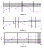
See the attached. This is an MLTL for a TB wideband driver. Lilac is the driver output, pink the vent / box output. For the three plots I've simply moved the location of the vent progressively up the enclosure. Otherwise same box, same vent dimensions, same damping: the tap location of the vent is the only difference. Upper plot = design location. Middle plot = halfway along the pipe. Lower plot = coincident with the driver. As you can imagine, the difference in the system response is quite significant.
Be that as it may, location of the duct as far as alignment is concerned can certainly make a difference depending on the aspect ratio of the enclosure and the presence or lack thereof of eigenmodes. A regular vented box assumes pure Helmholtz conditions, i.e. a uniform internal air particle distribution / density and no standing waves. An MLTL (or MLQW as I tend to call them) deliberately generates and uses the longitudinal standing wave as a functional part of the box tuning. The tap location of the duct into the pipe relative to the location of the pipe harmonics therefore can have a significant impact on load behavior.
See the attached. This is an MLTL for a TB wideband driver. Lilac is the driver output, pink the vent / box output. For the three plots I've simply moved the location of the vent progressively up the enclosure. Otherwise same box, same vent dimensions, same damping: the tap location of the vent is the only difference. Upper plot = design location. Middle plot = halfway along the pipe. Lower plot = coincident with the driver. As you can imagine, the difference in the system response is quite significant.
Attachments
I'd have thought BR was talked about that way in the interest of avoiding this kind of pipe behaviour. After all, if it isn't done deliberately then it may not have a positive result.
Very true. The point I was simply trying to illustrate is that some floorstanding boxes described as BRs et al have more in the way of longitudinal eigenmodes than is often realised. In which case it's better to assume there are some and either design, or plan, accordingly, which includes vent location. High proximity to the driver, as is shown, is far from automatically being optimal. I used the example above because it is not an extreme example of an MLTL & many would likely look at it & assume it was a regular vented box. I'm sure we can both think of umpteen similar examples.
Re the BR naming part, it's just my historical bent coming through. Thuras's original box & most of those up to & even after Novak did not share the same general alignment goals as a Small type vented box so I prefer to class them slightly differently (call it different subheadings) for that reason, under the OA Helmholtz basis. I appreciate I'm in the minority on this. 😉
Re the BR naming part, it's just my historical bent coming through. Thuras's original box & most of those up to & even after Novak did not share the same general alignment goals as a Small type vented box so I prefer to class them slightly differently (call it different subheadings) for that reason, under the OA Helmholtz basis. I appreciate I'm in the minority on this. 😉
Last edited:
Scott, do you still have that box to make some further measurements? I wonder if the coincident plot is due to being near the driver, or, as with the others, due to its placement along the line? Perhaps you could do another measurement to check that?
Also, is it possible that getting near the driver, the mic picked up driver radiation and caused the response issue? This is always an issue of course, but maybe perhaps the interaction is more variable with mic placement then I would have suspected.
Also, is it possible that getting near the driver, the mic picked up driver radiation and caused the response issue? This is always an issue of course, but maybe perhaps the interaction is more variable with mic placement then I would have suspected.
Last edited:
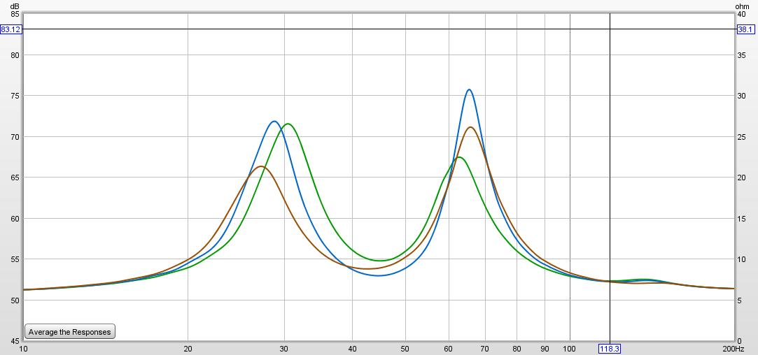
in my post #13 the graph shows the impedance curves for a 1 meter high floorstanding box, woofer placement is 75 cm up from floor:
green curve, upper port, 57 cm up from floor
blue curve, middle port, 37 cm up from floor
red curve, lower port, 14 cm up from floor
at about 140 hz there is some box related resonance shown, but i can not see where it comes from since there is no internal dimension that corresponds to that wavelength
See the attached. This is an MLTL for a TB wideband driver. Lilac is the driver output, pink the vent / box output. For the three plots I've simply moved the location of the vent progressively up the enclosure. Otherwise same box, same vent dimensions, same damping: the tap location of the vent is the only difference. Upper plot = design location. Middle plot = halfway along the pipe. Lower plot = coincident with the driver. As you can imagine, the difference in the system response is quite significant.
I can see differences but what do the sums look like?? You can see the output following the Q/Notch if they sum the same how can you hear the difference??
Rob 🙂
the thing is that it does make a difference where you put your vent, when other say it does not matter.
it would be interesting if they who say this does not matter showed proof for their statement.
it would be interesting if they who say this does not matter showed proof for their statement.
is it possible that getting near the driver, the mic picked up driver radiation and caused the response issue?
What Scott posted was a sim from a custom box we are working on. So no mic.
Yes, having the sum would also be helpful, but it seems fairly obvious that the last 2 examples havea depressed upper bass. Right where many like a bit of kick.
dave
A modified version of Martin King's MathCAD worksheets, the accuracy of which has been demonstrated for two decades and is sufficiently well-known not to need any further comment on my part.
WRT vent location, it's the internal tap location along the pipe that is being shown, which is what is relevant as far as the box load goes, assuming no additional boundary loading is applied (other external effects are a separate issue from the innate box load).
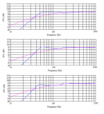
As noted, the system response is significantly affected; they certainly do not sum the same way. No surprises here for anyone familiar with QW type design. I didn't attach before because it was simply additional time that muggins here didn't have this afternoon (job of work to do -one day, they might even pay me). 😉 See attached. Same as above. Top = close to base, middle = half-way along the pipe, bottom = coincident with the driver.
WRT vent location, it's the internal tap location along the pipe that is being shown, which is what is relevant as far as the box load goes, assuming no additional boundary loading is applied (other external effects are a separate issue from the innate box load).
As noted, the system response is significantly affected; they certainly do not sum the same way. No surprises here for anyone familiar with QW type design. I didn't attach before because it was simply additional time that muggins here didn't have this afternoon (job of work to do -one day, they might even pay me). 😉 See attached. Same as above. Top = close to base, middle = half-way along the pipe, bottom = coincident with the driver.
Attachments
Last edited:
An obvious question, I guess. Do the MathCAD worksheets say anything about the differences between a bass-reflex enclosure where, in the style Joel was referring to in post #14, has been done in a box which has been specifically designed not to have modes close to the tuning frequency.. as opposed to a box which does happen to have modes near the tuning frequency, so makes use of the worksheet in that way by having the port placed considering these modes, and also happens to show the same response in the end?
Gain and a desire to create a coincident radiation source I suspect -IIRC that was why Thuras located them as he did.
Why would gain depend on the port location? Also, any conventional bass-reflex system will be a "coincident" radiation source, since the wavelengths involved are way larger than the woofer-port distance.
Be that as it may, location of the duct as far as alignment is concerned can certainly make a difference depending on the aspect ratio of the enclosure and the presence or lack thereof of eigenmodes. A regular vented box assumes pure Helmholtz conditions, i.e. a uniform internal air particle distribution / density and no standing waves. An MLTL (or MLQW as I tend to call them) deliberately generates and uses the longitudinal standing wave as a functional part of the box tuning. The tap location of the duct into the pipe relative to the location of the pipe harmonics therefore can have a significant impact on load behavior.
Agreed. But since a typical bass-reflex system will be designed to operate at low bass frequencies, the enclosure would have to be very tall (or specially designed MLTL system) to exhibit a standing wave at the bass-reflex tuning frequency.
I don't see how the operation or performance of a conventional bass-reflex system would depend on the location of the port. That said, the port location does make a difference when it comes to sound leakage at frequencies above the bass-reflex tuning frequency.
Why would gain depend on the port location? Also, any conventional bass-reflex system will be a "coincident" radiation source, since the wavelengths involved are way larger than the woofer-port distance.
Not inside the box. The goal is to have only the fundemental come out of the loudspeaker, but inside the box there is a train of odd harmonics going up in frequencies.
The length, taper, cross-section, Zd, and Zv all affect the structure of the shape of the internal waveform (eigenmodes) and what comes out the terminus. Unlike a reflex where the eigenmodes tend to naturally get LPed out, in a TL they are much more intense, and if the Holey Grail of taking out/LP all but the fundemental out of the terminus output.
dave
An obvious question, I guess. Do the MathCAD worksheets say anything about the differences between a bass-reflex enclosure where, in the style Joel was referring to in post #14, has been done in a box which has been specifically designed not to have modes close to the tuning frequency.. as opposed to a box which does happen to have modes near the tuning frequency, so makes use of the worksheet in that way by having the port placed considering these modes, and also happens to show the same response in the end?
If you're asking 'can you use them to model a box that doesn't have significant LF eigenmodes', the answer is 'yes, of course'. No problems there. Martin has some on his site, and I've used them many times for that, although generally speaking it's not necessary, or to put it another way, there is little reason to do so.
Not inside the box. The goal is to have only the fundemental come out of the loudspeaker, but inside the box there is a train of odd harmonics going up in frequencies.
Are you referring to standing waves and modes within the box? As I wrote above, these will only occur at frequencies way higher than the typical Helmholtz / bass-reflex tuning frequency. For example, a 90 cm tall box will have its lowest mode at about 190 Hz, whereas the bass-reflex system will be tuned somewhere at 50 Hz or lower. The bass-reflex tuning / Helmholtz resonance is therefore decoupled from the internal modes of the box.
(Yes, a MLTL is different, but the original question was about bass reflex, not MLTL)
They do. With a straight line with no complexity they will occur at the fundemental [F], 3F, 5F, 7F…. They directly affect the output of the terminus, and except for F, they become short enuff that distance plays a role. The 1st 2 are the biggest issue. So one gets ripple. One can move the magnitude and placement of the harmonics with geometric tricks like where the terminus is put.
Perhaps Scott can post a sim with no damping or other measures to supress the harmonics.
dave
Perhaps Scott can post a sim with no damping or other measures to supress the harmonics.
dave
They do. With a straight line with no complexity they will occur at the fundemental [F], 3F, 5F, 7F…. They directly affect the output of the terminus, and except for F, they become short enuff that distance plays a role. The 1st 2 are the biggest issue. So one gets ripple. One can move the magnitude and placement of the harmonics with geometric tricks like where the terminus is put.
Well, that's pretty much in line with what I wrote:
That said, the port location does make a difference when it comes to sound leakage at frequencies above the bass-reflex tuning frequency.
However, this leakage has nothing to do with the Helmholtz resonance of the bass-reflex box. Again, the operation and performance of the bass-reflex system (i.e., the Helmholtz resonator) does not depend on the woofer - port distance.
Yes, i knew from the last post of yours i replied to that we were talking the same thing.
Leakage, that term works, in any TL is a significantly more critical to deal with as the harmonics are purposely being let to pile up so that we can take advantage of the fundemental for bass extention. If they do not get adequately LPed from the terminus there is ripple in the bass.

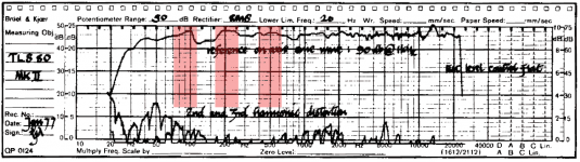
Anechoic measure of the FR of a TLS80, i have highlighted the peaks of the ripples in red. The dip below 200 Hz is exacerbated by baffle step — and the peak below is also lower than without BS. You can see in this end-loaded line that with no geomometric tricks (except for a bit of taper, to push the harmonics up), you can see that they ended up with some damping of the fundamental after they felt they had adequately damped the 3 and 5 harmonics.
A well designed ML-TL typically uses 2 tricks, an offset driver and a mass-loaded terminus, to geometrically create some LP function so that less damping has to be used ending up with the possibility of recovering more of the fundemental with little ripple.
Typically if you assume your “tower” is a BR and tune it as such, when measured the tuning is too high and a longer port has to be used. You see these kinds of posts often, hopefully less so these days. They have to be tuned lower because they are not a BR but an ML-TL.
dave
Leakage, that term works, in any TL is a significantly more critical to deal with as the harmonics are purposely being let to pile up so that we can take advantage of the fundemental for bass extention. If they do not get adequately LPed from the terminus there is ripple in the bass.
Anechoic measure of the FR of a TLS80, i have highlighted the peaks of the ripples in red. The dip below 200 Hz is exacerbated by baffle step — and the peak below is also lower than without BS. You can see in this end-loaded line that with no geomometric tricks (except for a bit of taper, to push the harmonics up), you can see that they ended up with some damping of the fundamental after they felt they had adequately damped the 3 and 5 harmonics.
A well designed ML-TL typically uses 2 tricks, an offset driver and a mass-loaded terminus, to geometrically create some LP function so that less damping has to be used ending up with the possibility of recovering more of the fundemental with little ripple.
Typically if you assume your “tower” is a BR and tune it as such, when measured the tuning is too high and a longer port has to be used. You see these kinds of posts often, hopefully less so these days. They have to be tuned lower because they are not a BR but an ML-TL.
dave
Attachments
For BR, it was stated-with a good reason, by a well respected designer, that the port should be as close to the woofer as possible, just like the speaker in post 6.
True, just as the original patent states, but this is based on the box being a true Helmholtz resonator, i.e. has a uniform particle density [no eigenmodes].
- Home
- Loudspeakers
- Multi-Way
- Disadvantage with putting the port far from the woofer?