Perry Marshall's Live Edge Dipoles inspired me to study them with the aim of developing my own variation on the theme. To do so, I had to develop Vituix models for the dipoles and for the Uframe, which I'd like to share. Perhaps someone can compare model predictions against their speakers.
Dipole modeling in Vituix is well known but running the model made clear that with dipole coax drivers, the coax mid woofer cone was being used over a much wider range than done in multi-way open baffle speakers and that there were consequences to that.
A U-frame model starts the same as a dipole model. Per Linkwitz, the acoustic impedance mismatch at the back of the U-frame attenuates the rear wave. Per Krekovsky, the U-frame's 1/4 wave resonance needs to be tamed which makes the Uframe response cardioid like in the low end.
I will do separate posts for each of my models

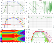
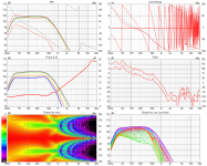
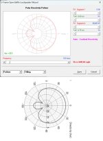
Starting with the model for the 8" Radian Audio 5208C's LF cone at the top of a baffle just wide enough to accomodate a 15" woofer at the bottom. My discussion/comments are in the schematic page of the simulation attached below and the simulation results are in the 6-pack export.
The polar response on the wide baffle caused me to consider tapering the baffle towards the top until it is just wide enough to securely support the 8" coax.
The polar response on the wide baffle caused me to consider tapering the baffle towards the top until it is just wide enough to securely support the 8" coax.
Attachments

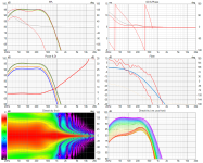
Now the same driver on a narrow/tapered baffle. The polar response is much nicer. The difference in the system simulation isn't huge however. The narrow baffle has only about .8 db less variation in its axial response due to this after optimization in the crossover.
Attachments
My plan is to use a single 15OB350 woofer, unlike the Bitch's Brew which use two or the Live Edge that uses a single 18" driver. The 15)B350 has 9405 mm3 volume displacement whereas the Kappa Pro18 LF has 9272 mm3, making them roughly equivalent in low end performance.
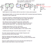
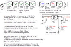
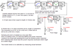
My first U frame analysis is attached below. The Uframe model differs from the dipole model in that rear wave has a 5.4 db attenuation caused by SPL division from the 1000 ohm acoustic impedance of the transmission line onto the 400 ohm acoustic impedance of air. This is from Linkwitz. It shows the response tending towards cardioid in the low end. The model looks usable past 300 Hz, where I'd like to crossover but doesn't account for the 1/4 wave resonance of the U frame. Thus, the next post.
My first U frame analysis is attached below. The Uframe model differs from the dipole model in that rear wave has a 5.4 db attenuation caused by SPL division from the 1000 ohm acoustic impedance of the transmission line onto the 400 ohm acoustic impedance of air. This is from Linkwitz. It shows the response tending towards cardioid in the low end. The model looks usable past 300 Hz, where I'd like to crossover but doesn't account for the 1/4 wave resonance of the U frame. Thus, the next post.
Attachments
John K describes the consequence of the Uframe resonance and how to treat it. Just today, AllenB posted a link to an archive of his website
link to post of JohnK site archive
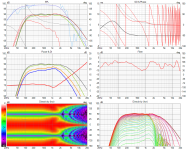
All my model does is add a low pass filter to the rear wave which I tune to flatten the power response. I rationalize that as saying that is roughly equivalent to what one would do in the lab, although JohnK suggests a different procedure. Ultimately, I think we are after the minimum damping that allows the Uframe to be used over the desired range.
With this damping model, we get a very cardioid like response, although the rear attenuation does fall off with frequency. Its not a concern that the response becomes cardioid as that has been shown to be most room placement independent and has a few db higher MaxSPL than a pure dipole.
link to post of JohnK site archive
All my model does is add a low pass filter to the rear wave which I tune to flatten the power response. I rationalize that as saying that is roughly equivalent to what one would do in the lab, although JohnK suggests a different procedure. Ultimately, I think we are after the minimum damping that allows the Uframe to be used over the desired range.
With this damping model, we get a very cardioid like response, although the rear attenuation does fall off with frequency. Its not a concern that the response becomes cardioid as that has been shown to be most room placement independent and has a few db higher MaxSPL than a pure dipole.
Attachments
I've been mulling over how bad these models are for a couple of days.
I recalled HornResp can model a U-frame and went there, using HR results to calibrate my model.
I was concerned about using the undamped Uframe with 15 cm sides above 200 Hz but realized damping would allow longer sides.
HR automatically added the amount of damping needed for a cardioid response. The cardioid rear rejection reduces with frequency, reinforcing the decision not to use these Uframes above 200 Hz or so.
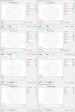
First attachment shows axial response (red) of damped and undamped Uframes with 15 cm and 30 cm sides.
These Uframes are essentially pipes with the woofer at one end and stuffing at the other.
The next two attachments are the HR calculated directivities.
I recalled HornResp can model a U-frame and went there, using HR results to calibrate my model.
I was concerned about using the undamped Uframe with 15 cm sides above 200 Hz but realized damping would allow longer sides.
HR automatically added the amount of damping needed for a cardioid response. The cardioid rear rejection reduces with frequency, reinforcing the decision not to use these Uframes above 200 Hz or so.
First attachment shows axial response (red) of damped and undamped Uframes with 15 cm and 30 cm sides.
These Uframes are essentially pipes with the woofer at one end and stuffing at the other.
The next two attachments are the HR calculated directivities.
Attachments
If I follow the track I'm on, I end up with a cardioid speaker instead of a dipole. That might not be a bad thing.
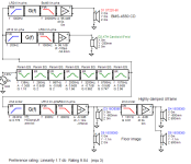
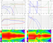
First attachment is the Vituix simulation circuit. This full range cardioid is uses mabat's 8" round top cardioid midwoofer model below a modification of his ST-260 waveguide (changed diameter to 220, changed beam width to 50 degrees).
The damped Uframe model is in the lower right corner. I tuned its low pass filter and rear attenuation to approximately match the HR models directivity at 100 Hz,
The simulation six pack is the next attachment. Its impressively good, even for a simulation.
Doing the same sim with the coax driver is on my todolist
Attachments
The alternative track is to preserve the dipole response. The undamped, tapered wing Uframes used in the Live Edge Dipoles bear only a family resemblance to the driver in a pipe the HR model is based on. The tapered wings present a range of delta path length between the front and rear wavefronts to a listener that should both smooths the frequency response and minimize or prevent the pipe resonances seen in the HR model from forming. If so, a good, simple_enough_for_Vituix model for them might be that of a dipole on a flat baffle with width equal to baffle width plus average wing depth across driver height, perhaps with a small attenuation.
This kind of model in a Vituix system simulation would and did give very attractive simulation results and is what got me started down this path.
I need to update those initial simulations and then decide if I like cardioid or dipole better.
This kind of model in a Vituix system simulation would and did give very attractive simulation results and is what got me started down this path.
I need to update those initial simulations and then decide if I like cardioid or dipole better.
I've taken my best shots at system optimization using wide and narrow baffles.
I'm modeling the tapered wing Uframe as a dipole; no attenuation or low pass filtering on the back wave. This seems most reasonable given what I've seen in the Live Edge Dipole measurements.
My optimization process is to tune for best compromise between smoothness on DI and PIR vs the axial response, as judged by the preference rating tool.
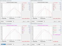
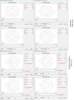
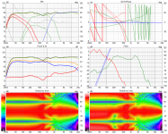
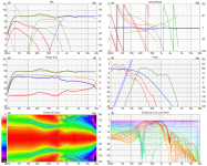
First up is the wide baffle crossed to the tweeter at 1600 hz. After manual optimization, the preference rating is 9.2 and the linearity is 3.5 db
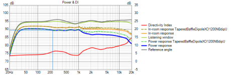
Next is the wide baffle crossed at 1200 Hz. After manual optimization, the preference rating is 9.3 and the linearity is 2.7 db. The overlays in its power DI chart are from the narrow baffle simulation.
Next is the tapered baffle crossed at 1200 Hz. Its preference rating is 9.6 and linearity is 1.6 db
In restrospect, the widening of the response towards the high end of the coax's mid woofers response results in a big dip in the axial response and a peak in the PIR and power response around 650 Hz for the wide baffle and about 800 Hz for the narrow baffle. Preference scores for wide baffle crossed at 1200 Hz are nearly equivalent to those of the narrow baffle.
I'm modeling the tapered wing Uframe as a dipole; no attenuation or low pass filtering on the back wave. This seems most reasonable given what I've seen in the Live Edge Dipole measurements.
My optimization process is to tune for best compromise between smoothness on DI and PIR vs the axial response, as judged by the preference rating tool.
First up is the wide baffle crossed to the tweeter at 1600 hz. After manual optimization, the preference rating is 9.2 and the linearity is 3.5 db
Next is the wide baffle crossed at 1200 Hz. After manual optimization, the preference rating is 9.3 and the linearity is 2.7 db. The overlays in its power DI chart are from the narrow baffle simulation.
Next is the tapered baffle crossed at 1200 Hz. Its preference rating is 9.6 and linearity is 1.6 db
In restrospect, the widening of the response towards the high end of the coax's mid woofers response results in a big dip in the axial response and a peak in the PIR and power response around 650 Hz for the wide baffle and about 800 Hz for the narrow baffle. Preference scores for wide baffle crossed at 1200 Hz are nearly equivalent to those of the narrow baffle.
Attachments
-
 TBdipoleXO1600WBdipU XO-schema-1.png22.3 KB · Views: 156
 -
 TBdipoleXO1600WBdipU Six-pack.png96.9 KB · Views: 136
 -
 TBdipoleXO1200WBdipU XO-schema-1.png22.8 KB · Views: 132
 -
 TBdipoleXO1200WBdipU Six-pack.png95.9 KB · Views: 139
 -
 TaperedBaffleDipoleXO1200NBdipU XO-schema-1.png22.4 KB · Views: 124
 -
 TaperedBaffleDipoleXO1200NBdipU Six-pack.png81.9 KB · Views: 143
One of my design objectives has been to minize the response dip to the floor reflection, which usually occurs around 350 Hz. By crossing between midwoofer and woofer at nominally 300 Hz, I get some overlap that has the desired effect. Operating the Uframe that high introduces concerns about pipe resonances in the Uframe. These are reduced by limiting its depth, which in turn limits the low end extension. To get the best of both worlds, one needs to introduce damping into the Uframe, which turns it into a cardioid. Experimenting with that, I found I didn't like the transition from cardioid woofer to dipole midwoofer. It had a wid axial peak there because one can hardly expect cardioid directivity to match that of a dipole, except perhaps with a very lightly damped Uframe cardioid that is transitioning to dipole at the high end of its range. that was the objective in the simulation whose results are attached below, but it wasn't achieved
Attachments
Models are not 100% accurate. I am not sure what type of model is used in VituixCAD. I just use them as a rough guide, then I have to buy, build, and measure to know what is really going on.
There is a speaker by Emerald Physics that got good reviews when it was produced. You might find some inspiration in the design:
https://www.theabsolutesound.com/articles/emerald-physics-cs23-mk-ii-loudspeaker/
Some pics showing the driver layout, etc. can be found here:
https://tmraudio.com/old-products/emerald-physics-cs2-3-open-baffle-speakers-excellent-pair-cs-2-3/
To manage floor bounce I use the Allison approach: put the woofer right at floor level, as low as possible. Cross over as high as 300Hz to the midrange, which should be as high as possible (like the coax on top placement). This gives the woofer the most floor gain to the highest frequency possible, and the midrange has the least amount of floor bounce effects.
This trail led me to the full range cardioid, posted earlier and repeated below. the tweeter and cardioid mid responses are derived from the round top cardioid and ST-260 waveguide by mabat. Still undetermined is how much I can extend the depth of the now damped Uframe and still get cardioid response past 300 Hz but these simulation results are very encouraging. I should also point out that I'm simulating separate waveguides and midwoofer instead of a coax. This has always been a temptation, given there is ample room on the baffle between where the coax would be and the 15OB350 woofer at floor level.
Attachments

Thanks for that link, Charlie. the tapered baffle with rounded top is exactly what I have in mind. the double woofer plus coax is the same as Perry Marshall's Bitch's Brew speaker. I'm trying to get away with a single 15, augmented with subs, to save my back when I need to move the speakers.Models are not 100% accurate. I am not sure what type of model is used in VituixCAD. I just use them as a rough guide, then I have to buy, build, and measure to know what is really going on.
There is a speaker by Emerald Physics that got good reviews when it was produced. You might find some inspiration in the design:
https://www.theabsolutesound.com/articles/emerald-physics-cs23-mk-ii-loudspeaker/
Some pics showing the driver layout, etc. can be found here:
https://tmraudio.com/old-products/emerald-physics-cs2-3-open-baffle-speakers-excellent-pair-cs-2-3/
To manage floor bounce I use the Allison approach: put the woofer right at floor level, as low as possible. Cross over as high as 300Hz to the midrange, which should be as high as possible (like the coax on top placement). This gives the woofer the most floor gain to the highest frequency possible, and the midrange has the least amount of floor bounce effects.
As to mistrusting simulations, I agree with you 100%. That doesn't stop me from using them to try and understand design approaches and decide if one is worth building and measuring. Vituix calculates 3D response fields from anechoic/quasi anechoic measurements of drivers on baffles. In the absence of measurements, it has the tools to synthesize approximations from data sheet traces plus piston directivity based on driver Sd and baffle shape.
You are an open baffle expert and afficionado. What do you have to say about cardioid vs OB regarding which does better in an untreated room?
I've never tried/built, or listened to, a cardioid system so I cannot offer any opinion on them, versus a dipole, etc.
I believe Perry also used a rear CD+horn in his Bitches Brew LED speaker, probably to even out the power response in that band. It's definitely an issue/challenge when using a coax mid+HF unit.
I think your single 15 idea could work, maybe. I tried a bunch of pro audio drivers but using the woofer nude, with the idea that it could run up to 300Hz, but I always felt I could hear/perceive cone resonances. Now I use four 8" home audio woofers in a 20x20 inch baffle. I've built a couple of systems like that and I think the approach works pretty well. By using a series-parallel or 4-parallel electrical connection you can raise the sensitivity quite a lot, and even above what most pro drivers can deliver. But bass is still limited to about 70-80 Hz due to the limited total displacement of the drivers, with Xmax typically only about 6mm, so I also cross over to CB subs around that frequency.
As I recall, Linkwitz asserted that cardioid wasn't superior to OB but Kimmosto demonstrated impressively flat room response for a cardioid inside a small fully tiled bathroom.
Yes Perry does use a rear firing tweeter/waveguide. You can see its simulated effect in the overlays of the attachment
Yes Perry does use a rear firing tweeter/waveguide. You can see its simulated effect in the overlays of the attachment
Attachments
Last edited:
I can understand why there is little interest in OB simulations given how easy it is to experiment. Nevertheless, I have limited build facilities so I prefer to do most of my cut and try in simulation. As an EE with an ASIC background, simulation is in my blood.
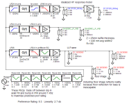
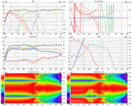
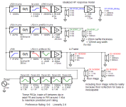
The first attachment is what my OB simulations have led me to. At the top is a Radian Audio 5208C coax. At the bottom is a SB Audience 15OB350. In between is a 10" woofer. I'm using a Dayton RS-270 as a place holder but its the weak link due to its 100 W RMS power limit, which is just barely enough. I will have a rear facing CD/horn as in @perrymarshall's designs. The second attachment is a screenshot from the Vituix simulation.
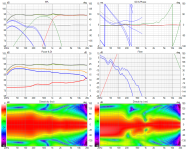
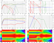
The initial goal was just a coax over a Uframe woofer. I found I needed a bridge driver between them if the coax was to be at or near ear height to keep the pattern constant width up to the coax. With this configuration, I get almost perfect flat axial response with the smoothest falling power response I've seen. Per the preference rating tool, it achieves a linearity of .6 db combined with a preference score of 9.89 out of 10. True, this is only simulation and reality won't be nearly as good but this tells me that the speaker architecture is near ideal, or perhaps has no major mistakes.
As you can see in the polar map, the H polar response is almost perfectly flat. This is a result of minimizing the baffle width around each driver. Too much baffle width or too deep U-frame wings and the pattern widens at the high end. I know @CharlieLaub has gone to zero baffle for mid range and tweeter and the compromised pattern with too much baffle probably explains why. I'm hoping I've tapered my baffle enough to be within epsilon of a no-baffle design. Likely there are more compromises due to use of a coax rather than separate mid and tweeter but I'm enamored of single point sources above Shroeder.
I first simulated the Uframe in HornResp to see the pipe resonances in it. With a 300mm depth, 100 Hz is a conservative low pass cut off frequency. It can probably be pushed up to 125 Hz and perhaps 150 Hz but there is no need to do so here.
You can do an IB enclosure simulation in Vituix with the same filters used for low end boost and flattening in the main simulation to determine the max SPL of a dipole or Uframe. Doing that, I learned the bridge driver could easily handle its 100 Hz high pass with the baffle as shown and that the coax didn't need any baffle for a 300 Hz high pass. It does need to be supported so it has a baffle only for its lower half.
Can a single 15" driver in a 300 mm Uframe provide enough bass? Not unless you don't play very loud, which I no longer do. I have a design target of >= 105 db MaxSPL and simulation shows the 15OB350 can get to -3db in the low 30s at that level. I won't know if its enough until I hear it.
I simulated a sealed 15" woofer in place of the U-frame but the Vituix room tab showed me boundary interference issues in the 60 Hz to 100 Hz range. So if one has a sealed bottom end, it should be crossed over no higher than 60 Hz, requiring the mid driver to play down that low. Perhaps the new 10" Purifi woofer can do that. I understand why Charlie plans to use 4 of them at the bottom of his design. I'm tempted to do that myself but it would blow my weight budget. My decision so far is to keep the Uframe and use separate subs if I find I need/want them.
The first attachment is what my OB simulations have led me to. At the top is a Radian Audio 5208C coax. At the bottom is a SB Audience 15OB350. In between is a 10" woofer. I'm using a Dayton RS-270 as a place holder but its the weak link due to its 100 W RMS power limit, which is just barely enough. I will have a rear facing CD/horn as in @perrymarshall's designs. The second attachment is a screenshot from the Vituix simulation.
The initial goal was just a coax over a Uframe woofer. I found I needed a bridge driver between them if the coax was to be at or near ear height to keep the pattern constant width up to the coax. With this configuration, I get almost perfect flat axial response with the smoothest falling power response I've seen. Per the preference rating tool, it achieves a linearity of .6 db combined with a preference score of 9.89 out of 10. True, this is only simulation and reality won't be nearly as good but this tells me that the speaker architecture is near ideal, or perhaps has no major mistakes.
As you can see in the polar map, the H polar response is almost perfectly flat. This is a result of minimizing the baffle width around each driver. Too much baffle width or too deep U-frame wings and the pattern widens at the high end. I know @CharlieLaub has gone to zero baffle for mid range and tweeter and the compromised pattern with too much baffle probably explains why. I'm hoping I've tapered my baffle enough to be within epsilon of a no-baffle design. Likely there are more compromises due to use of a coax rather than separate mid and tweeter but I'm enamored of single point sources above Shroeder.
I first simulated the Uframe in HornResp to see the pipe resonances in it. With a 300mm depth, 100 Hz is a conservative low pass cut off frequency. It can probably be pushed up to 125 Hz and perhaps 150 Hz but there is no need to do so here.
You can do an IB enclosure simulation in Vituix with the same filters used for low end boost and flattening in the main simulation to determine the max SPL of a dipole or Uframe. Doing that, I learned the bridge driver could easily handle its 100 Hz high pass with the baffle as shown and that the coax didn't need any baffle for a 300 Hz high pass. It does need to be supported so it has a baffle only for its lower half.
Can a single 15" driver in a 300 mm Uframe provide enough bass? Not unless you don't play very loud, which I no longer do. I have a design target of >= 105 db MaxSPL and simulation shows the 15OB350 can get to -3db in the low 30s at that level. I won't know if its enough until I hear it.
I simulated a sealed 15" woofer in place of the U-frame but the Vituix room tab showed me boundary interference issues in the 60 Hz to 100 Hz range. So if one has a sealed bottom end, it should be crossed over no higher than 60 Hz, requiring the mid driver to play down that low. Perhaps the new 10" Purifi woofer can do that. I understand why Charlie plans to use 4 of them at the bottom of his design. I'm tempted to do that myself but it would blow my weight budget. My decision so far is to keep the Uframe and use separate subs if I find I need/want them.
Attachments


Not many responses (apart from Charlie) but my guess is that there are many followers/viewers if this thread.
I look forward to seeing how your build compares to your simulation. Or, how the simulation can be tweaked to more closely match reality. 😉
But isn’t it amazing how much we can simulate with VituixCAD2- from box modelling to shaping the baffle to driver positioning to crossover modelling? Without ever having to cut a single sheet of timber?
Good luck with your project!
How does VituixCAD account for the large motor structure that is "in the way" to the rear of the coax when it creates a model of the SPL and power responses? Or do you use measurements to generate those plots?
Also, IMO placing the coax at the top edge of a baffle that is only about as wide as the driver frame is a good way to make the pattern behave well. This was done commercially in for example the Emerald Physics CS2.3
Also, IMO placing the coax at the top edge of a baffle that is only about as wide as the driver frame is a good way to make the pattern behave well. This was done commercially in for example the Emerald Physics CS2.3
Attachments

IME, better to have multiple smaller motors with near equal cone surface area where dipole operation is implemented as Charlie indicated. That strategy would also eliminate the need for that filler driver you’ve found necessary in your simulations.
Where weight is a concern, the offset could be neo drivers of your budget can spare the expense. You can also do a modular approach as the lx521……four 8” woofers in a hybrid W frame would give you a near perfect seated on axis ear height for your coax driver. Doing so would allow you some experimental baffle shapes for the coax as well. I believe Linkwitz’s simulations only took him so far to creating the strange top hat baffle we see in the 521. Remember crude experimenting can be simple with just the clever use of thick cardboard and some tape or a little hot glue.
Where weight is a concern, the offset could be neo drivers of your budget can spare the expense. You can also do a modular approach as the lx521……four 8” woofers in a hybrid W frame would give you a near perfect seated on axis ear height for your coax driver. Doing so would allow you some experimental baffle shapes for the coax as well. I believe Linkwitz’s simulations only took him so far to creating the strange top hat baffle we see in the 521. Remember crude experimenting can be simple with just the clever use of thick cardboard and some tape or a little hot glue.
Charlie: thanks for your tips. You pointed me towards the Emerald Physics baffle originally.How does VituixCAD account for the large motor structure that is "in the way" to the rear of the coax when it creates a model of the SPL and power responses? Or do you use measurements to generate those plots?
Also, IMO placing the coax at the top edge of a baffle that is only about as wide as the driver frame is a good way to make the pattern behave well. This was done commercially in for example the Emerald Physics CS2.3
My VituixCad dipole and U-frame simulations are based on two cones in baffles, one facing forward and one backwards separated by the baffle thickness or U-frame depth, with their responses synthesized in the Vituix diffraction tool and then summed in the main simulation.
The kind of detail like the effect of blocking by the driver frame and magnet is available using ABEC3/AKABAK. You draw the driver cone and magnet structure in CAD with the U-frame around them and export STL or a mesh to ABEC that does a BEM simulation with polar response output files that can be massaged back into Vituix. Its a lot of work to get the CAD and then the mesh of adequate quality but perhaps something to do when its too cold to go outside to build or measure. Since I'm only using the U-frame up to 100 Hz I'm going to wave my hands and say since the magnet diameter is a small fraction of the wavelength it can be ignored.
That isn't the case for the coax driver however. The frame and magnet structure will have a much greater effect. There, I'm just crossing my fingers and hoping for the best 🙂
Actually, I'm relying on the work of others, @perrymarshall in particular, for proof That that the 5208C coax driver is worthy of an OB build,
That is really the goal of these simulations: to show that the system architecture and driver choice work and, given also the rich history of OB builds, this design is worth prototyping.
- Home
- Loudspeakers
- Multi-Way
- Dipole and Uframe models and discussion re' Live Edge Dipoles