Thank you torgeirs!@mark100 You seem to have full control over all filters and windows in your signal chain. That is impressive😀
Yes, open architecture processors, found commonly in proaudio install, allow for easy individual control...(and experimentations!)
The problem is that it was in the time domain that I looked. And I didn’t find any ringing in the FIR crossover on the sine and on the music signal, but in the IIR crossovers I saw much more interesting pictures.@uriy-ch Transients occur in music. And is best viewed in time domain
I'm sometimes confused by people asking me if I can hear the ringing of the FIR crossover I'm using. To this day I cannot understand what ringing they are asking me about.
This is exactly correct. It is easy to design complementary filters whose responses cancel mathematically. But such perfect summation cannot be guaranteed in an acoustic space. There are path-length differences, reflections, driver response differences, and other factors that may allow for perfect summation at one location but not at another.Summing two speaker elements is another story. Thats why people messure polar plots, DI and power transfer function
This is all true, but I often see the opinion that FIR filters have a pre-echo, so IIR is better. But I was unable to catch this before the echo using measurements of the DSP output signal. And I don’t understand, either I caught it poorly, or there is still no ringing in the FIR. You are good at mathematics. Can you give an answer, if the IR of the FIR filter has a pre-echo, will there be some kind of echo in the signal, and if so, how to measure it on a real signal, or the echo from the filter in the useful signal is still fiction, i.e. misinterpretation of IR FIR view?This is exactly correct. It is easy to design complementary filters whose responses cancel mathematically. But such perfect summation cannot be guaranteed in an acoustic space. There are path-length differences, reflections, driver response differences, and other factors that may allow for perfect summation at one location but not at another.
The pre-echo will be present in the signal but, depending upon its amplitude and duration, it may not be easily visible. It may be obscured by other parts of the signal. Recall that we perceive sound amplitude logarithmically, so something that is very small when displayed on a linear scale may still be quite audible.... if the IR of the FIR filter has a pre-echo, will there be some kind of echo in the signal, and if so, how to measure it on a real signal ...
Ok, while i have this experiment up and running...i can give easily you 550Hz instead of 300Hz.And now I’m very interested in seeing ringing in the DSP passband, i.e. roughly speaking, I want to see ringing on a 300Hz sine wave with a 300Hz FIR crossover.
From measured acoustic response.
Here's the sections of 3-way unity horn using 96 dB/oct linear phase xovers at 550Hz and 4000Hz.
The 3-way is designed for use with sub, so the low section (red) above, has a 100Hz lin phase high pass in it. (same 96dB/oct)
Slight impulse pre-ring is visible in full speaker below, which will cancel when combined with complementary sub)
Can't take an impulse of a sine wave, but can put a scope on it.
Here's 550Hz on-axis, two 10" lows, and a compression driver, using stated lin phase xover.
40 degrees off-axis, near the edge of the 90deg conical horn pattern, looks identical.
Guassian wavelets are an interesting test for crossovers, as they at least show some differnce under speaker rotation.
Here's a 550Hz wavelet. Green is on-axis, red is 40 deg.
I really don't know what the post wavelet ringing in the 40 deg is, maybe diffraction ?? (conical horn has 90 degree H pattern)
But I don't think it has anything to do with the xover.
Oh, btw...in case anyone is wondering...
This is the same speaker shown as a 4-way in #104. But without the mid-section drivers.
I changed the xover point for the low and HF via new FIR filters, since they can reach together. (See raw response in 104)
That's all it takes to change xover frequencies using steep complimentary linear phase. Delays don't even change, between the 4-way and 3-way version.
Mag and phase both stay flat on-axis, either version. All the work either way, as always ime, is measuring/choosing xover points for smoothest obtainable polar response.
Fine.The pre-echo will be present in the signal but, depending upon its amplitude and duration, it may not be easily visible.
How to catch the pre-echo measurements?
As I understand it, pre-echo applies to all types of signal, i.e. on the sinus I should also see before the echo. How to measure (see) with a DAC-ADC pre-echo in the time domain?
Regarding the pre- and post-echoes: Markw4's question was related to different types of DAC interpolation filters. DAC interpolation filters have cut-off frequencies that are supposed to be ultrasonic, so their pre- and post-ringing is also at supposedly ultrasonic frequencies.
However, these filters are often filters with a passband ripple designed with some variant of the Parks-McClellan algorithm (which itself is based on the Remez exchange algorithm). The passband ripple causes a pre- and a post-echo at non-ultrasonic frequencies. Those are the ones I meant.
I doubt if this is relevant for FIR loudspeaker crossover filters, because I understand from mark100's and Lars Risbo's comments that they are usually designed with windowed inverse DFTs rather than with Parks-McClellan. Besides, I wonder if the echoes aren't obscured by the pre- and post-ringing when the filter cut-off is in the middle of the audio band.
Marcel, yes important to distinguish between the pre echo like in the upsampling/decimation filters and general pre ringing from phase linear bandwidth limitation. Personally, I would like to know if say a sharp 30Hz high pass phase linear response has audible pre ringing?
The ADC complicates the problem. The best way to see any ringing is probably with contrived digital signals, i.e., with impulses or square waves created in the digital domain. That's cheating, because they violate the Nyquist Criterion, but they will trigger the impulse responses of any filters that exist in the digital processing.How to catch the pre-echo measurements?
As I understand it, pre-echo applies to all types of signal, i.e. on the sinus I should also see before the echo. How to measure (see) with a DAC-ADC pre-echo in the time domain?
Step response taken from impulse response is the easiest to see.Fine.
How to catch the pre-echo measurements?
There will be negative response below step peak. Sounds more like pre-echo than anything else i think.
And It's mainly indicative of a system linear-phase high-pass. (subwoofer or main speaker without sub)
System high-pass and low-pass have no complementary xover off-set to cancel pre-ring. IIR for those.
Otherwise, if the speaker has achieved decent measured complementary acoustic crossovers using linear-phase,
I vote 'just say no to pixel-peeping the impulse response for any pre-ring'. It's a concern about nothing ime/imo.
I tend to agree with this. For any pre-ring shorter than about 20 milliseconds, backward masking will likely render it inaudible. https://www.ansys.com/blog/what-is-auditory-maskingOtherwise, if the speaker has achieved decent measured complementary acoustic crossovers using linear-phase,
I vote 'just say no to pixel-peeping the impulse response for any pre-ring'. It's a concern about nothing ime/imo.
My experience is that a sharp linear phase system high pass can sound like a pre-echo.Personally, I would like to know if say a sharp 30Hz high pass phase linear response has audible pre ringing?
Kind of like hearing a very faint drum whack before the loud real one. Could be heard both indoors and out.
Reminds me of the sound of a powerful firecracker, right before explosion, .....the sound of air sucking inward before going boom..
This was with a 72 dB/oct high-pass at around 30-31Hz. Twas all the tap count could pull, that I had available at the time.
I haven't bothered with any further linear phase system high pass work , other than trying to figure out how weave it with IIR to get the most benign phase alteration, but still safe high-pass, possible.
Just my 2c impressions 🙂
You mean a half-wavelength at 4kHz, right? With a full wavelength being 0.25ms, & 0.125ms for half wavelength.@mark100 Could you insert a half wavelength delay on HP filter at the 4k filter, about 5 cm or 1,5 ms?
Please:
-magnitude
-phase
-group delay
And maybe one at 0.7 ms or about 90 degres phase difference?
Assuming so, here's a 0.125ms delay on the VHF section (4kHz up)
Black impulse is summation of all 3 driver sections. And lays on top of the time delayed VHF impulse.
In mag, phase and group delay below impulse, phase is referenced to full speaker impulse peak, which equals VHF peak. Blue is group delay.
Here's 1/4 WL delay (0.0625ms)
What are you after? Trying to see?
Ringing in general is refering to exciting a filter with acramp functionThe problem is that it was in the time domain that I looked. And I didn’t find any ringing in the FIR crossover on the sine and on the music signal, but in the IIR crossovers I saw much more interesting pictures.
I'm sometimes confused by people asking me if I can hear the ringing of the FIR crossover I'm using. To this day I cannot understand what ringing they are asking me about.
For 2. order filters a critically damped filter with no ringing has Q of 0,5. Q above this has ringing in the time domain
The peaks of the group delay for the sum get bigger as the filter order increase when a delay is introdusedWhat are you after? Trying to see?
At some level that group delay variance can be heard
Yes, the ADC has its own internal digital signal processing which imposes its own IR on the signal it measures. But, if we believe that the signal that passed through the DSP and received FIR processing has a pre-echo in the audible region of the frequency range, then whatever one may say, we should see this using an ADC that has its own IR, just as the ADC covers audible frequency range. Otherwise, the cause-and-effect relationship is broken. It’s as if there is an echo, but it’s not in the measurements.The ADC complicates the problem.
Fine.The best way to see any ringing is probably with contrived digital signals, i.e., with impulses or square waves created in the digital domain.
I have a DAC with DSP on board.
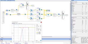
I'm putting together this circuit.

As you can see from the figure, my first channel is direct without an FIR crossover.
I divide the second channel into three bands using an FIR crossover, then I sum the three bands and output the result to the DAC output.

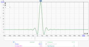
Here is a file for REW in which there are real measurements of each DAC channel according to the diagram. Tell me which of these measurements passed through the FIR crossover, and why you decided so.
Attachments
- Home
- Loudspeakers
- Multi-Way
- Digital Signal Processing - How it affects phase and time domain