If all were from the same bank, you should have read 47 ohms x 2 for all 3.
I have no clue how you're getting 1 ohm for the two reading that low.
I have no clue how you're getting 1 ohm for the two reading that low.
There are 2 pnp and 2 npn driver transistors per bank of fets
so 3 fets have 1 pair of drivers the other 3 fets have another set of drivers .
So I’m having issues with both sets of drivers or a transformer is shorted or something .
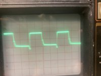
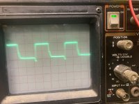
The drive signal looks good with a loading cap but as soon as the fets are installed the drive signal goes bad .
here is what I get as far as resistance
Q9-Q9A 94.1 ohms
Q9-Q9B 94.1 ohms
Q9A-Q9B 94.1 ohms
Then
Q12-Q12A 93.3 ohms
Q12-Q12B 93 ohms
Q12A-Q12B 93.1 ohms
Q9-Q12 is 1.020K ohms
These readings match all of the other banks of fets as well .
so 3 fets have 1 pair of drivers the other 3 fets have another set of drivers .
So I’m having issues with both sets of drivers or a transformer is shorted or something .
The drive signal looks good with a loading cap but as soon as the fets are installed the drive signal goes bad .
here is what I get as far as resistance
Q9-Q9A 94.1 ohms
Q9-Q9B 94.1 ohms
Q9A-Q9B 94.1 ohms
Then
Q12-Q12A 93.3 ohms
Q12-Q12B 93 ohms
Q12A-Q12B 93.1 ohms
Q9-Q12 is 1.020K ohms
These readings match all of the other banks of fets as well .
There is a 1N4148 in series with a zener diode for each bank of FETs. Lift the 1N4148s and try again.
I removed the 4148’s
I still get 93 ohms from gate pad to gate pad on Q9,Q9A,Q9B and 1k ohms from Q9 to Q12 this is how it’s supposed to be I’m guessing since all of the other banks have the same measurements
Q9,Q9A,Q9B are driven by Q7B,Q8B drivers
Q12,Q12A,Q12B are driven by Q7C,Q8C drivers
I still get 93 ohms from gate pad to gate pad on Q9,Q9A,Q9B and 1k ohms from Q9 to Q12 this is how it’s supposed to be I’m guessing since all of the other banks have the same measurements
Q9,Q9A,Q9B are driven by Q7B,Q8B drivers
Q12,Q12A,Q12B are driven by Q7C,Q8C drivers
Last edited:
Do I leave the 4148’s out of circuit and put the fets back in circuit and look at the waveforms ?
Ok I replaced the diodes and it fixed the problem . Thanks greatly appreciate it .
The original rectifiers that were in the amp were FMG36R and 36S
Since the legs were broken and fixed with solder I replaced them with APT30D60BCAG and APT30D60BCTG.
The negative rectifier is the BCTG?
The original rectifiers that were in the amp were FMG36R and 36S
Since the legs were broken and fixed with solder I replaced them with APT30D60BCAG and APT30D60BCTG.
The negative rectifier is the BCTG?
Ok the bctg suffix is the positive rectifier.
Wondering if the schematic is wrong if I install the rectifiers according to the schematic the amp draws excessive current
Wondering if the schematic is wrong if I install the rectifiers according to the schematic the amp draws excessive current
Once I install the rectifiers and power the power supply board up how long should I let it idle on bench ? Just to see if any problems occur before putting the amp back together and putting it in vehicle
The output board is disconnected from the power supply board right now .
So I have just the power supply board sitting on the bench . I can power it up without a heatsink or I can put it back in the heatsink I just wanna let it idle for awhile to make sure no other issues arise
So I have just the power supply board sitting on the bench . I can power it up without a heatsink or I can put it back in the heatsink I just wanna let it idle for awhile to make sure no other issues arise
Idling won't show much but 10-15 minutes should show any problems.
When it's all together, longer testing would be warranted, especially if you can't test to full power on the bench.
What do you have for a power supply on the bench?
When it's all together, longer testing would be warranted, especially if you can't test to full power on the bench.
What do you have for a power supply on the bench?
- Home
- General Interest
- Car Audio
- Digital Designs Z2HV