Hmmm….you’re grounding the digital MUSES pins to the analog supply of the IP. I, personally, am not comfortable with that. I’d prefer not to ground the MUSES digital grounds to the analog grounds. Especially as MUSES went to the trouble of galvanically isolating them according to @mvaldes. I’d go to the extra trouble of keeping that galvanic isolation in a project like this.
You show 5VD as standalone but I’m assuming you’re deriving that from the +15VDC of the IP supply - again personally, I’d make that an independent PS and ground that PS and all the (right-side) MUSES digital grounds to that and safety earth. But that’s just me….🙃
You show 5VD as standalone but I’m assuming you’re deriving that from the +15VDC of the IP supply - again personally, I’d make that an independent PS and ground that PS and all the (right-side) MUSES digital grounds to that and safety earth. But that’s just me….🙃
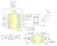
I appreciate your comments. What I posted wasn't the complete schematic. The one below also includes the 5V regulator and digital isolator. Feel free to look it over and post your comments. At the moment the Vreg and digital isolator is on order. I should have it within a few days then I can check if it works as drawn.
It's all pretty much experimental. I'm making changes and testing on breadboard as I go along. Only when I'm happy that it's working 100% will I order boards from the fab house.
PS. Right now 5VD (probably not named correctly) on Muses pin 17 is powered from the ESP32 which runs on either USB or an external power source.
Attachments
Last edited:
Hmmm….you’re grounding the digital MUSES pins to the analog supply of the IP. I, personally, am not comfortable with that. I’d prefer not to ground the MUSES digital grounds to the analog grounds. Especially as MUSES went to the trouble of galvanically isolating them according to @mvaldes. I’d go to the extra trouble of keeping that galvanic isolation in a project like this.
You show 5VD as standalone but I’m assuming you’re deriving that from the +15VDC of the IP supply - again personally, I’d make that an independent PS and ground that PS and all the (right-side) MUSES digital grounds to that and safety earth. But that’s just me….🙃
Would you also make separate supplies for the analog and digital +/-15V pins?
Just a side note about the schematics that I’ve posted so far. If anyone copies anything I post, you do so at your own risk. I’m not trained in electronics, so it's pretty obvious that improvements can be made to my circuits. I therefore welcome all comments and constructive criticism. Please feel free to make suggestions, point out flagrant errors, etc.
But please also note that most of what I posted has been working for me on breadboard and sounds great... and it's very quiet (apart from the music). I have a working Muses72320 circuit that’s been changed a few times. It’s running on an ESP32 and displaying smooth fonts on a beautiful hi-res LCD screen. The electronics and code are certainly not perfect, but hey, I’m getting there.
But please also note that most of what I posted has been working for me on breadboard and sounds great... and it's very quiet (apart from the music). I have a working Muses72320 circuit that’s been changed a few times. It’s running on an ESP32 and displaying smooth fonts on a beautiful hi-res LCD screen. The electronics and code are certainly not perfect, but hey, I’m getting there.

If we are talking about the MUSES 72323/72320, I believe the bipolar supply (up to +/-18VDC) is strictly for the analog ‘side’ of the chip and the digital ‘side’ requires 5VDC - I.e, there’s no digital +/-15VDC.Would you also make separate supplies for the analog and digital +/-15V pins?
I appreciate your comments….
To be honest, I haven’t paid a lot of attention to the 72320 as I intend using the 72323. Assuming your 72320 Out’s (to the IP) are not the Gain outs then your schematic should work. A few comments/queries -
- Why are you using caps on the audio out of the MUSES?
- I’d consider incorporating 47R, good quality, resistors in series with the audio outs.
- From memory, the ADum1300 does have level translation so your use of different level supplies (3.3VDC in and 5VDC out) isn’t an issue but a quick look at the 1300’s datasheet just to confirm should clear that up.
- I don’t know what maximum current output the ESP32 can provide to auxiliary devices but I assume you’ve checked that and are within the current max for the devices (ADuM, display(?), IR rcvr(?) you intend using.
- Again from memory, the 72323 has three pins connected to the bipolar positive rail and three pins connected to the bipolar negative rail - does the 72320 only have two pins each rail connected?
So, all that said and aside from my aversion to grounding the MUSES analog and digital grounds to the IP’s 0V rail along with taking the 5VDD supply from the IP as stated above, I’d think that should work. But, in my humble opinion, it’s not an optimised implementation for the MUSES/IP project. I’d buy a small donut like ZM said and use your on-order regulator with that for the clean side and that’d allow you to redo your ground scheme to allow separation of the audio ground, the ESP32 and it’s auxiliary devices (the ‘dirty’ digital side) and the ‘clean side’ MUSES digital 5VDD requirement and isolator VDD2 and VDD2 GND. Would only require the purchase of a small xfmr.
Last edited:
iirc the 72323 has pins for digital +5V, digital +15V, digital -15V, analog-R +15V, analog-R -15V, analog-L +15V and analog-L -15V. As soon as we join the three +15V and -15V pins together we are likely to get digital noise into the analog part, right? So if we separate AGND from DGND we should also separate digital +/-15V from analog +/-15V, no...?
The ‘digital’ part we want to separate ‘from the rest’ is the potentially noisy digital control logic signals. MUSES appear to have gone to the trouble of isolating this and therefore requiring it be powered by its own PS - the 5VDC D_IN pin 16 and grounded separately by D_REF on pin 32. Hence also the use of the isolator on those logic control pins. I suspect you are looking at pins 21 and 28 and seeing the reference to digital power supply plus and minus but they are not part of the control logic according to the diagram on page 7 of the datasheet.
No, I’m not using gain on the Muses (although it’s external opamps). In my opinion there is no point in using gain if it’s used with the IP which already has built-in gain.To be honest, I haven’t paid a lot of attention to the 72320 as I intend using the 72323. Assuming your 72320 Out’s (to the IP) are not the Gain outs then your schematic should work. A few comments/queries -
You’re raising very good questions, which I’ll happily answer.
Because Wayne used caps there in the Pass Labs XP-12 preamp. There is a picture in post #2. Many other users’ schematics also show it, so I though why not.
- Why are you using caps on the audio out of the MUSES?
After discussing those resistors with Zen Mod, he suggested losing them when used with the IP.
- I’d consider incorporating 47R, good quality, resistors in series with the audio outs.
Done and confirmed.
- From memory, the ADum1300 does have level translation so your use of different level supplies (3.3VDC in and 5VDC out) isn’t an issue but a quick look at the 1300’s datasheet just to confirm should clear that up.
On full brightness, the Waveshare 2.4” LCD screen draws 14mA. The other devices draw even less, so all good I think.
- I don’t know what maximum current output the ESP32 can provide to auxiliary devices but I assume you’ve checked that and are within the current max for the devices (ADuM, display(?), IR rcvr(?) you intend using.
Correct. Only two pins for the 72320.
- Again from memory, the 72323 has three pins connected to the bipolar positive rail and three pins connected to the bipolar negative rail - does the 72320 only have two pins each rail connected?
Your aversion and concerns about not using a separate transformer to power the Muses data block are noted. However, the voltage regulator that I’ve ordered is made by Nisshinbo Micro Devices, the same company who manufactures the Muses chips. One would think that they approve of using the two products together in the way I intend to do. BTW, this specific voltage regulator was suggested by @mvaldes who seems to have a lot more electronics knowledge than I and he’s also built a Muses attenuator (and used the same regulator and digital isolator). See post #124.So, all that said and aside from my aversion to grounding the MUSES analog and digital grounds to the IP’s 0V rail along with taking the 5VDD supply from the IP as stated above, I’d think that should work. But, in my humble opinion, it’s not an optimised implementation for the MUSES/IP project. I’d buy a small donut like ZM said and use your on-order regulator with that for the clean side and that’d allow you to redo your ground scheme to allow separation of the audio ground, the ESP32 and it’s auxiliary devices (the ‘dirty’ digital side) and the ‘clean side’ MUSES digital 5VDD requirement and isolator VDD2 and VDD2 GND. Would only require the purchase of a small xfmr.
Part of the fun of diy is the design decision-making process, thanks for answering the queries.
I will likely use an external LT3045-based PS for the two digital rails - certainly overkill but I have it on hand - the best reason. The Analog Devices LT3045 datasheet shows a noise spec of between 0.8uV and 2.5uV at full load (500mA) and ripple rejection of 117dB. As compared to the MUSES NJM78L05 datasheet which shows ratings of 70uV and 69dB.
I will likely use an external LT3045-based PS for the two digital rails - certainly overkill but I have it on hand - the best reason. The Analog Devices LT3045 datasheet shows a noise spec of between 0.8uV and 2.5uV at full load (500mA) and ripple rejection of 117dB. As compared to the MUSES NJM78L05 datasheet which shows ratings of 70uV and 69dB.
That was my thinking originally, but the datasheet suggests otherwise, because all GNDs are tied together anyway. Plus with the IP, audio GND is tied to PS GND and no way to get around that, unless one uses an external 15V supply. Since the Muses works fine with the IP's +-15V, I won't bother.The ‘digital’ part we want to separate ‘from the rest’ is the potentially noisy digital control logic signals. MUSES appear to have gone to the trouble of isolating this and therefore requiring it be powered by its own PS
In the end they all go to ‘ground’, yes. At chassis ground. As shown by the datasheet, yes.
But my interpretation of the 72323 datasheet is that trying to separate the noisier digital logic control block’s ground from audio ground seems to have been a design objective of MUSES. And this seems to be borne out by @mvalde’s confirmation the two grounds are indeed galvanically isolated in the chip.
So why not implement it separately as MUSES imply by trying to keep the audio ground ‘lifted’ somewhat (NTC, resistor etc) from the noisier digital ground? Yes, your approach of lumping all the grounds together will work but, again, if the two grounds on the chip are indeed galvanically isolated then the intention was clearly to offer you the opportunity to go the extra mile and implement it separately. Otherwise they would simply have joined the grounds internally.
No reason why you can't do it that way. I have what you're describing on breadboard and it works very well. Maybe we're busy cultivating a culture of "more is better" here, while the simpler circuits work just as well.
So, go for it, but breadboard it first, then transfer the design to PCB. I didn't and ended up with a blown Muses chip. Part of the reason could be that I'm using the IP's 15V binary PSU and not an external power source for the Muses 15V.
So, go for it, but breadboard it first, then transfer the design to PCB. I didn't and ended up with a blown Muses chip. Part of the reason could be that I'm using the IP's 15V binary PSU and not an external power source for the Muses 15V.
There’s a school of thought that might argue the noise generated by the incoming digital signals (Data, Clock and Latch) will be reduced by the isolator before getting into the MUSES and therefore less noise will pollute digital ground in the MUSES. Matter of how far you want to go to keep noise out/down.
In the DIY mindset the justification is, “I’ll sleep better knowing I beat it into submission”. In the EE mindset….ask an EE.
After my previous posts I received some messages from members with questions regarding my boards.
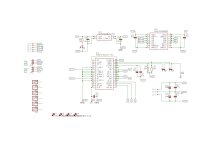
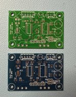
Here are the schematic and Gerber file I made for the muses 72323 and 72320.
They share basically the same logic, so there is a digital isolator for the microprocessor control signals and a 5V regulator to derivate the 5V for the Muses chip from a +15/0/-15 analog power. I choose this solution because I made these board to use on my IP and also for other projects.
I still have some board available, if someone wants them send me a DM.
Michele
Attachments

Excellent, @mvaldes.
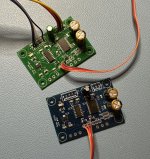
It looks like the signal's in/output correspond with the spacing on the IP boards. How do you mount the Muses boards vertically on the IP boards and how is the connection made? Can it plug in and out?
Now I understand your logic with the isolator and 5V regulator. By using that, no external power supply is needed for the Muses because both the binary 15V and 5V required for the Muses digital block are sourced directly from the IP boards. Also, any MCU & screen can be used. Your design is very flexible. It can be mated to a simple Arduino MCU and OLED screen, or alternatively, a fancy high-res LCD screen requiring more RAM, in which case a more powerful MCU can be used. The only external power needed would be for the selected MCU and screen.
Also, with provision being made to change the Muses chip address by jumper, one MCU can control two of your boards for balanced IP boards.
Last edited:
For USA, this one might be a place to start if you like to roll your own. I could see using 4 or 5 of these to control 8 to 10 channels:
https://www.ti.com/product/LM1972
They have a few other ones too:
https://www.ti.com/audio-ic/amplifiers/volume-control-ics/products.html
https://www.ti.com/product/LM1972
They have a few other ones too:
https://www.ti.com/audio-ic/amplifiers/volume-control-ics/products.html
- Home
- Amplifiers
- Pass Labs
- Digital Control of Attenuation – Repository for DIY