I can’t remember why they are there and can’t test as I am not at home. It is probably debounce and needed. Are you sure the 20 milliseconds will screw your code?I'd like to try your code, but the delay() pauses will really screw up the other functions in my sketch. Can it be made to work without delay()?
Delays can ruin a lot of stuff, also interrupts can make things sluggish: but if interrups only set a flag that will be polled later on I prefer to not use interrupts at all. The video gives good code for encoders, but again using interrupts - my version is smaller (inspired by this code, see google cache) and gets away without interrupts:
I think with todays fast mcus there is need to handle buttons or encoders with interrupts - I want my mcu to get through the stuff I need the power for first and do the buttons and encoders as soon as time allows. That's in most cases fast enough for me. But my version can use interrupts, only one line of code more is needed:
BTW if ESP32 can't make use of elapsedMillis.h you can easily re-write the stopwatch parts in my button library to use micros() or whatever call is suitable on ESP32. Or even replace micros() and millis() in elapsedMillis.h with the ESP32 versions...
C#:
const uint8_t pinA = 6, pinB = 7;
boolean chanA, chanB;
int8_t oldstate = 3;
int enc = 0, val = 0, old = 0, counter = 0;
const uint8_t detents = 3;

const int8_t enctable[] = {0, -1, 1, 0, 1, 0, 0, -1, -1, 0, 0, 1, 0, 1, -1, 0};
// table with half resulution that can be used for encoders with too high resolution or for very bad encoders:
// const int8_t enctable[] = {0, 0, -1, 0, 0, 0, 0, 1, 1, 0, 0, 0, 0, -1, 0, 0};

void setup() {
  Serial.begin(115200);
  pinMode(pinA, INPUT_PULLUP); pinMode(pinB, INPUT_PULLUP);
}

void loop() {readEnc();}

void readEnc() {
  chanA = digitalRead(pinA); chanB = digitalRead(pinB);
  int8_t state = chanA | (chanB << 1);
  if (oldstate != state) {
    enc += enctable[state | (oldstate << 2)];
    if (state == detents) val = enc >> 2;
    oldstate = state;
  } interpretEnc();
}

void interpretEnc() {
  if (val > old) {counter++; Serial.println(counter); old = val;}
  else if (val < old) {counter--; Serial.println(counter); old = val;}
}
I think with todays fast mcus there is need to handle buttons or encoders with interrupts - I want my mcu to get through the stuff I need the power for first and do the buttons and encoders as soon as time allows. That's in most cases fast enough for me. But my version can use interrupts, only one line of code more is needed:
C#:
const uint8_t pinA = 6, pinB = 7;
boolean chanA, chanB;
int8_t oldstate = 3;
int enc = 0, val = 0, old = 0, counter = 0;
const uint8_t detents = 3;

const int8_t enctable[] = {0, -1, 1, 0, 1, 0, 0, -1, -1, 0, 0, 1, 0, 1, -1, 0};
// table with half resulution that can be used for encoders with too high resolution or for very bad encoders:
// const int8_t enctable[] = {0, 0, -1, 0, 0, 0, 0, 1, 1, 0, 0, 0, 0, -1, 0, 0};

void setup() {
  Serial.begin(115200);
  pinMode(pinA, INPUT_PULLUP); pinMode(pinB, INPUT_PULLUP);
  attachInterrupt(pinA, isr, CHANGE); attachInterrupt(pinB, isr, CHANGE);
}

void loop() {interpretEnc();}

void isr() {
  chanA = digitalRead(pinA); chanB = digitalRead(pinB);
  int8_t state = chanA | (chanB << 1);
  if (oldstate != state) {
    enc += enctable[state | (oldstate << 2)];
    if (state == detents) val = enc >> 2;
    oldstate = state;
  }
}

void interpretEnc() {
  if (val > old) {counter++; Serial.println(counter); old = val;}
  else if (val < old) {counter--; Serial.println(counter); old = val;}
}
BTW if ESP32 can't make use of elapsedMillis.h you can easily re-write the stopwatch parts in my button library to use micros() or whatever call is suitable on ESP32. Or even replace micros() and millis() in elapsedMillis.h with the ESP32 versions...
Last edited:
About the AGND -> DGND topic again:

This is my schematic so far. I have dedicated +5V and +/-15V regulators in my PSU. I have 3 GNDs now (marked in red). "GND1" will be joined with the mcu. Looking at the schematics by meldano, lalaina and others it seems that if no isolator is used GNDA is separated from GND, but if the Muses IC sits behind an isolator GNDA and GND are joined (hence I put a solder jumper in between GNDA and GND). I guess it depends on how "dirty" we consider the digital block of the Muses IC, right?
This is my schematic so far. I have dedicated +5V and +/-15V regulators in my PSU. I have 3 GNDs now (marked in red). "GND1" will be joined with the mcu. Looking at the schematics by meldano, lalaina and others it seems that if no isolator is used GNDA is separated from GND, but if the Muses IC sits behind an isolator GNDA and GND are joined (hence I put a solder jumper in between GNDA and GND). I guess it depends on how "dirty" we consider the digital block of the Muses IC, right?
I use millis exclusively in ESP32 code, and no delays. Thanks for the code. I'll experiment and see which works best, but only later. Right now I'm concentrating on getting my board designed so I can send the Gerbers to the fab house. Software refinements will come later as it is 95% complete.BTW if ESP32 can't make use of elapsedMillis.h you can easily re-write the stopwatch parts in my button library to use micros() or whatever call is suitable on ESP32. Or even replace micros() and millis() in elapsedMillis.h with the ESP32 versions...

Thanks for the hint! Yes, at the end of the day all GNDs must be at 0V, be it via the chassis or connected elsewhere. I still don't understand the difference between closing the jumper (with a solid connection of course) or joining the GND of the 7805 with GND1 at the dirty side of the isolator, because I don't know how the Muses IC works internally: does it use digital VDD only for the logic and the analog path is fully isolated? Do the +/-15V supplies only power internal gain stages or is the output signal affected by the quality of the +/-15V even if we always turn off gain settings? In other words: does the attenuation happen separately from all the logic like with a relay attenuator?
Last edited:
it's really boiling to just one fact, then one can decide what to do with own OCD:
- are Digital GND and Audio GND galvanically isolated in MUSES chip itself?
if yes, do with your own OCD whatever you want
if no, choose where to make them physically connected in circuit (think DA chips and tying those two at specific pin of DA chip itself)........
I can't check the fact, because I didn't found the fact in datasheets (maybe I didn't read them thoroughly) and because sole MUSE chip I have in possession I got already soldered and it'll keep collecting virtual dust ............
edit: while I was typing, jpk (finally someone) wrote the same thing
This is what I had been working on. You could select the source name from a list, a trim for quieter sources, a balance that would trim the left or right channel down proportionally, auto dim the display, choose the display colour and simple web app. I had not started on the hardware side yet but was planning to have a 12v trigger and a relay that would ground the speakers (anti pop). I spent more time trying to display the album cover being played on PiCorePlayer than anything else and lost interest. I will have another go, like I posted before I could not get a touchscreen to display so I will get another one as it is probably faulty. I was fairly happy with the user interface it was looking and working better than some high end stuff that is out there.
@Zen Mod
maybe I'm wrong but I've only wrote that in the jpk schematic there is a conceptual mistake. There is no ground connection for the 7805 besides the jumper. That, for my point of view, have no meaning. Why putting a jumper when need a stable connection ?
That being said, I totally agree with you.
PS: all ground pin on Muse chip (D or A) are galvanically isolated between them
PS: all ground pin on Muse chip (D or A) are galvanically isolated between them
thus confirmed - then no need of isolating anything, just have separate audio and digital PSUs, connect digital GND to chassis/safety GND, lift audio GND from chassis in some of usual ways of controlled lifting
if building gadget without safety GND (double isolation standards), then improvise with isolator chip solutions or whatever
OK, thanks for clarifiy! The Muses72323 even has separate +/-15V pins for digital and analog: so do I need another dual supply?
The jumper is only there to illustrate the possible connection - it's not the final schematic. Also there is a screw terminal at GND of the 7805 that was intended to connect somewhere else in case the jumper stays open...
@Zen Mod
jpk schematic there is a conceptual mistake. There is no ground connection for the 7805 besides the jumper. That, for my point of view, have no meaning. Why putting a jumper when need a stable connection ?
The jumper is only there to illustrate the possible connection - it's not the final schematic. Also there is a screw terminal at GND of the 7805 that was intended to connect somewhere else in case the jumper stays open...
As I don't intend to sully His Mightiness' IP bipolar supply by taking any feed off it to drive a digital input (horrors!) just for the sake of convenience or to save a few cents in a project of the IP's quality why not simply use a dual-rail, separate PSU for all the digital components and leave the IP bipolar supply to do what it was intended to do? 🙂
In previous projects with microcontrollers controlling DACs I've always used the above approach - one rail for the 'dirty' microcontroller and IR, display, relay coils etc and the second, separate (no CT), rail for the 'clean' side of the isolator and DAC. I can't see any reason not to do the same for the MUSES. Second, 'clean', rail for digital in/D_REF on the MUSES and VDD2/GND2 of the iso chip. And grounding is as ZM outlined with NTC.
I don't have my 72323 in hand yet but @mvaldes has confirmed the digital and analog grounds on the 72323 (presume same on 72330 but worth checking) are galvanically isolated so above scheme should work. Audio grounds (L_REF, R_REF etc) I'd ground to the IP's 0V. Unless HMZM advises a better scheme...🙂
Unless HMZM
as I wrote earlier, that's exact recipe I'm using in my Iron Pumpkin and few other concoctions
audio circuits having own Donut & rest of PSU, while small 10VA Donut dedicated for relays and logic circuitry (based on Arduino Mega 2560 Pro, I need plenty of relays to command)
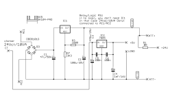
nothing fancy, simplest possible
edit: IC1 is LM317, ignore error in note - IC2 is not needed when logic is not used in particular project)
Attachments
If someone is interested of using a PIC microcontroller with OLED SPI display, I have uploaded HEX file here
Last edited:
Hey guys, do you have any schematic files for Muses72323 which you could share here?
I started drawing it from scratch in KiCad and came across this thread.
I started drawing it from scratch in KiCad and came across this thread.
I put in a request for the 72323 to be added at SnapEDA but haven’t checked whether they did the schematic/pattern yet. You can perhaps have a look there. I did mine from scratch (with elongated solder pads to help with the 0.65mm spacing 🙃) but I use Diptrace so not sure if that will import into KiCad. In the interim you could look for SSOP 32 components in KiCad and edit pin names?Hey guys, do you have any schematic files for Muses72323 which you could share here?
I started drawing it from scratch in KiCad and came across this thread.
componentsearchengine.com has symbols, footprints & 3D models for the Muses72323 as well as Muses72320.
Thanks for bringing that up @derekr. Since posting that diagram in post #130, I have changed the schematic and verified that it works with all GNDs connected to AGND. I'll ask admin to replace that diagram with the correct one.
In the meantime, have a look at what the schematic looks like in Kicad now.
In the meantime, have a look at what the schematic looks like in Kicad now.
Attachments

- Home
- Amplifiers
- Pass Labs
- Digital Control of Attenuation – Repository for DIY