Thanks Steve. I realise that I meant to say that we could create an in phase and 0dB summing 18dB/octave sloped cross where the response is -6dB at the crossover.
I was a newbie - I still am, and I was once thoroughly confused by the "4" of the LR4. Getting past that was a rite of passage. Crossover design is no longer a black art. It is at worst a grey art. (The truly advanced stuff is still black, but the basics are white.) It dawned on me that "quasi" should be prefixed to all these terms.
Last edited:
It never occurred to me the important relationship between group delay and driver offset, but I must learn it to master this grey art.
So, am I getting it correct... I took a woofer measurement with a mic with an acoustic reference (seems to be an impulse) from the tweeter. Now the woofer phase data will have the driver offset embedded in it, no? And the final design will show a group delay curve with a sudden jump before and after the crossover point, corresponding to the driver offset? And I change crossover slopes (to change group delay) until that sudden jumps becomes not so sudden? (I mean there are many ways to change group delay but my understanding is that changing slopes is the most "flat" way to do so.)
So, am I getting it correct... I took a woofer measurement with a mic with an acoustic reference (seems to be an impulse) from the tweeter. Now the woofer phase data will have the driver offset embedded in it, no? And the final design will show a group delay curve with a sudden jump before and after the crossover point, corresponding to the driver offset? And I change crossover slopes (to change group delay) until that sudden jumps becomes not so sudden? (I mean there are many ways to change group delay but my understanding is that changing slopes is the most "flat" way to do so.)
Last edited:
If you measure with something like Holmimpulse, the delay is retained. The phase will wrap, conspicuously toward the top end. You can modify the delay until it looks like a normal phase plot.
If you measure each driver in succession without moving the mic, the relative delay is retained. If you apply the same amount of delay compensation to both of the drivers, one will remain slightly wrapped. The slope differences should be obvious at this point.
If you measure each driver in succession without moving the mic, the relative delay is retained. If you apply the same amount of delay compensation to both of the drivers, one will remain slightly wrapped. The slope differences should be obvious at this point.
Unfortunately in this step simulation doesn't help at all, every of that seems good.
I think you are not using the simulator correctly. You cannot simply use the manufacturers frequency response graphs because they are all made on an IEC baffle.
The proper way is to take measurements of your woofer and tweeter in the actual box you are using. You will find they are quite different.
Then, enter the frd and zma files in Jeff Bagby's PCD7. The simulations will give you an idea of how the crossover behaves.
I thought I might have made a mistake: in XSim if I choose "derived phase" that would eat away the driver offset from my phase measurement, right?
Yes. It will also incorporate the effects of diffraction by assuming they are minimum phase. Polar measurements will bring them back, or you can choose to round the cabinet and move on..
Thanks for your help. I get it now. I didn't find looking at the group delay curve to be useful any more. (It tells me the problem, not the solution.) I think most people simply look at the phase curve and make sure that looks smooth (both drivers, and overall), right?
I think you are not using the simulator correctly. You cannot simply use the manufacturers frequency response graphs because they are all made on an IEC baffle.
The proper way is to take measurements of your woofer and tweeter in the actual box you are using. You will find they are quite different.
Then, enter the frd and zma files in Jeff Bagby's PCD7. The simulations will give you an idea of how the crossover behaves.
Of course, absolutely right, but unfortunately I haven't enough space (and time) to make this, having to do everything in my listening domestic space. By time I'm looking for a system to take measurement more accurate as possible but I couldn't. I think I'll try a kind of "tunnel" with insulating wall, as a shelving covered with duvets or something similar, between panel and mic, can you suggest me a better and not expensive method?
Thank you for the suggested application.
However, would you explain in few words what can be differences in sound between a 1'' soft dome like mine and the horn tweeter used in your Nightingale V, cutted @ 1.5 Khz? I'v enever listened similar drivers in my room and I'm wondering why not to follow your path. May it be suited for a domestic ambient?
..or in alternative I can try tweaking your beautiful "Falcon", inserting that 2'' midrange coupled with my Scanspeak D2905-950000, removing any doubts upon cross frequency..
However congratulations for your very nice projects!
However congratulations for your very nice projects!
With regards to the listening axis response. For me, this is one of the last processes as other things tend to change it or invalidate assumptions.I think most people simply look at the phase curve
I drew this picture to illustrate to other beginners and help them visualize how the master "combines" the acoustic and the electrical crossover:
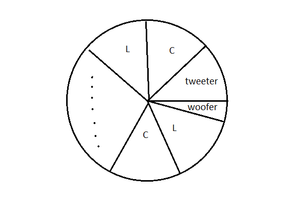
For a quasi-LR4, the two drivers are in phase because they are always 360 degrees apart and therefore come full circle. Both the tweeter and the midrange participates in the phase shift, but they meet somewhere near 180 degrees to complete the circle. For example, the tweeter could go 190 degrees forward and the woofer -170 degrees. If they do not meet at exactly 180 degrees, no harm done, it just isn't a symmetrical LR4 on the graph. Phase symmetry is highly unlikely to be audible and should be low on your priority list.
Each low pass reactive element always goes from 0 degrees at 0Hz to -90 degrees at infinite Hz. Each high pass reactive element always goes from 90 degrees at 0 Hz to 0 degrees at infinite Hz. At exactly the crossover frequency, the phase shift has to be somewhere in the proximity of +/-45 degrees.
Both Butterworth and Linkwitz-Riley are 45 degrees at the crossover point. So it takes 8 reactive elements (4 inductors + 4 capacitors) to complete the circle if the acoustic phase shifts of the drivers themselves are the same.
But you can use the Chebyshev alignment. On average, in my experience, you can shift about 60 degrees with each reactive element. It is only a ballpark and it is impossible to give an exact figure because each situation is different. You can go back to 45 degrees or even less, or be aggressive and get more than 60 degrees.
The acoustic shifts are measured, and they are known. If each reactive element shifts 40-70 degrees there are only so many ways you can divide the remainder of the pie.
This explains the "order" of the electrical crossover and how it combines with the "order" of the acoustic crossover. Combine != add and 1 + 1 is not necessarily 2 in this process, but the pie chart helps you visualize what is going on.
Attachments

...The BW2 looks bad on frequency response, but conceals a secret. It has overall flat power response and flat impedance. Both good things, IMO.
And we can fix the frequency response with a 90 degree phase shift in a crossover by mucking up the time alignment between the two drivers.
This is what the BBC did in the LS3/5A speaker by stepping the bass back on the baffle. A surprising solution that worked for a lot of people.
Thank you system7 for sharing such a thought-provoking example which exemplifies the practicality of such a timeless classic.
I now realize that flat power response and flat impedance are one and the same thing.
A phase-coherent quasi-LR design on the other hand has an impedance peak at the XO frequency which corresponds to its power response dip.
Three things, pick only 2: flat FR, flat power, on-axis main lobe. BW2 has flat power and on-axis lobe but not flat FR. This classical example illustrate how one trades the on-axis lobe for flat FR. Because of the bass driver offset the lobe axis is now skewed.
However, would you explain in few words what can be differences in sound between a 1'' soft dome like mine and the horn tweeter used in your Nightingale V, cutted @ 1.5 Khz?
I find horns have more depth in the music compared to dome tweeters. By depth, I mean the front to back distance in the sound stage.
The highs are also more focused and it has "throw". In other words, the treble doesn't die off as fast as a dome tweeter when you move farther away from the speakers.
These are just my opinions. It doesn't mean horns are superior to domes. There are good horns and bad horns as there are good dome tweeters and bad dome tweeters.
Mike
..or in alternative I can try tweaking your beautiful "Falcon", inserting that 2'' midrange coupled with my Scanspeak D2905-950000, removing any doubts upon cross frequency..
However congratulations for your very nice projects!
I don't think it's go idea to try to tweak the Falcon. It takes a lot of experience to do a proper crossover.
If you like, I can design a crossover for you using your 830869 with a HiVi TN28. This way, you can put your 830869 to good use. Keep your Scanspeak for future projects.
Mike
What you would hear is higher non-linear distortion in the Butterworth design because both the HF and LF drivers are being pushed 3dB harder at the XO frequency.Before you rush out and dig into Butterworth, let me clarify further: in an anechoic chamber, on-axis, they sound the same (other than the sound difference between higher-order crossovers and lower-order crossovers). This is because you wouldn't be able to hear power response in an anechoic chamber and by definition both give flat on-axis responses.
- Status
- Not open for further replies.
- Home
- Loudspeakers
- Multi-Way
- Differences in tweeter's sound by different kind of crossover