This is actually a time delay and is dealt with differently.
How so? This thread is, in no uncertain terms, a passive thread, not a DSP thread.
You can use a Bessel all-pass filter to approximate a constant time delay, but it will never be exact across all frequencies like a DSP. I think I had an active crossover for car lying around which had that.
In practice all passive crossovers fix time delay by treating it as a phase shift.
Of course, the "best" is to fix the driver offset and make it zero. But the "best" is in quotes because in practice that usually gives rise to other issues, or is impractical.
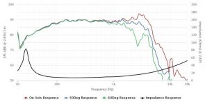
An amusing afternoon looking at the Peerless 830869 8" Nomex woofer.
I've got one for about the usual 30 Litres of reflex for this Qts 0.38 woofer.
It's definitely not a nice woofer for 3kHz crossover, but I'd start here with something based loosely around that old KEF tweeter filter.
Michael Chua found a 1.5kHz crossover more suitable, but that used a horn tweeter. A different animal entirely. http://ampslab.com/nightingale_v.htm
Attachments
...the C2C (center-to-center) between midrange and tweeter decides the lobing pattern...
If one can get the C-C down to a quarter wavelength at the XO point, many of the issues involved go away, making for a much less “evil” XO — the drivers become essentially coincident. This is not usually possible with a cone+dome 2-way and one of the reasons for increasing interest in WAW (Woofer Assisted Widerange). The Peerless should make a decent helper woofer, most of its issues go away when you cross it at 250-450 Hz to a good 3 or 4 inch FR.
dave
Well! Excuse me for the late, I'll tell you all about my experience. My project comes straightly from a "New Vifa Tower" by Murphy Blaster realised some years ago. That sounded very very nice, the mid region was wonder but not the bass one, so I started to try changing woofer and crossover, just to begin learning something about, strongly helped by Boxsim by Visaton and frd and zma files traced from manufacturer specs.
I'm an "old beginner", studied architecture and not electronics but "transfer function" is always in my mind..! So before of all I put New Vifa Tower in Boxsim and realised a certain agreement between the real model used as reference and its virtual simulation.
That system used a Vifa 8'' woofer (M21WO39-08, which has a wonderful response) and a ScanSpeak D2905-9500 (in reality Murphy talked about a "Scaspeak 9500", so D2905-9500 was my supposition), with a 3rd order crossover configuration. Its response in mid and treble region was very very good, and the cross-point was at about 2 Khz, and this proves what was said by Scottmoose. In particular, tweeter never had any sound problem.
Here simulation of that New Vifa Tower:


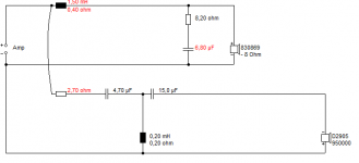
Since I love the mid-bass response of Peerless P830869 I tried to put it beside D2905-9500 I already own, and in effect, cutting it highly, trebles was very "aggressive" and unpleasant, probably due to its peaking in 3 Khz region. So I discovered that the best way to shoot down breakup was inserting a RC in parallel to the baffle-step big inductor, and so Peerless was fixed well.
From this point, problems appeared to tweeter. Cutting it high it sounded thin and clinking; cutting lower it sounded with a quite "metallic" taste; cutting even lower trebles was better but "ssss" and cymbals are in big evidence, even lowering trebles level....
Here simulation of the last stage overlyed to New Vifa Tower.


In effects, cross-point is just a bit down 2 Khz (say 1.85, proved by some real measurement in domestic ambient), 10 uF is the only way to avoid metallic response but.... it's still not good, quite sibilant and brilliant.
Where do I go wrong?!
@System7: thank you but how do you manage 3 Khz breakup with 1.5 mH coil? and why don't you reverse tweeter polarity?
@ Cyberstudio: no need to apologyse, as you can see I'm less than a beginner..
@ Jonathan Bright: yes, is certainly a "black art", I'm just wondering about..
@Michael Chua: 1.85 Khz
@Linesource: thank you for your alternative tweeter advices
@all: what does it mean "beaming" and "lobing" please..?
@all: thank you very much!
I'm an "old beginner", studied architecture and not electronics but "transfer function" is always in my mind..! So before of all I put New Vifa Tower in Boxsim and realised a certain agreement between the real model used as reference and its virtual simulation.
That system used a Vifa 8'' woofer (M21WO39-08, which has a wonderful response) and a ScanSpeak D2905-9500 (in reality Murphy talked about a "Scaspeak 9500", so D2905-9500 was my supposition), with a 3rd order crossover configuration. Its response in mid and treble region was very very good, and the cross-point was at about 2 Khz, and this proves what was said by Scottmoose. In particular, tweeter never had any sound problem.
Here simulation of that New Vifa Tower:
Since I love the mid-bass response of Peerless P830869 I tried to put it beside D2905-9500 I already own, and in effect, cutting it highly, trebles was very "aggressive" and unpleasant, probably due to its peaking in 3 Khz region. So I discovered that the best way to shoot down breakup was inserting a RC in parallel to the baffle-step big inductor, and so Peerless was fixed well.
From this point, problems appeared to tweeter. Cutting it high it sounded thin and clinking; cutting lower it sounded with a quite "metallic" taste; cutting even lower trebles was better but "ssss" and cymbals are in big evidence, even lowering trebles level....
Here simulation of the last stage overlyed to New Vifa Tower.
In effects, cross-point is just a bit down 2 Khz (say 1.85, proved by some real measurement in domestic ambient), 10 uF is the only way to avoid metallic response but.... it's still not good, quite sibilant and brilliant.
Where do I go wrong?!
@System7: thank you but how do you manage 3 Khz breakup with 1.5 mH coil? and why don't you reverse tweeter polarity?
@ Cyberstudio: no need to apologyse, as you can see I'm less than a beginner..
@ Jonathan Bright: yes, is certainly a "black art", I'm just wondering about..
@Michael Chua: 1.85 Khz
@Linesource: thank you for your alternative tweeter advices
@all: what does it mean "beaming" and "lobing" please..?
@all: thank you very much!
IMO I think this link explains beaming really well: Speaker Off Axis: "Correct" Driver Diameters for Great Off Axis Response - Acoustic Frontiers
Your intended application also plays a role. I believe so far everyone has been assuming this is for general hi-fi, which it sounds like it is. E.g. for a studio nearfield monitor the dispersion requirements are different.
Your intended application also plays a role. I believe so far everyone has been assuming this is for general hi-fi, which it sounds like it is. E.g. for a studio nearfield monitor the dispersion requirements are different.
Here is the link to the discussion thread: Pt. 2: Audibility of Crossovers
This test is hardly dispositive.
You would think that in a competitive speaker market with smart designers, that such an obviously superior topology would be dominant.
If one can get the C-C down to a quarter wavelength at the XO point, many of the issues involved go away, making for a much less “evil” XO — the drivers become essentially coincident. This is not usually possible with a cone+dome 2-way and one of the reasons for increasing interest in WAW (Woofer Assisted Widerange). The Peerless should make a decent helper woofer, most of its issues go away when you cross it at 250-450 Hz to a good 3 or 4 inch FR.
dave
Indeed. I am really intrigued by this quarter wave project, touted as a single point source: Pushing the limits of small speakers - The Reference Mini build thread
This is, however, in another league and totally beyond my limited capability.
This test is hardly dispositive.
You would think that in a competitive speaker market with smart designers, that such an obviously superior topology would be dominant.
I felt the same - and that's why I repeatedly disclaimed that in the real world your design needs the crossover type which fits best, not basing any decisions on any sweeping generalizations.
But, under the ideal condition, the logic is so sound as to be irrefutable, isn't it.
On the other hand, the Linkwitz-Riley paper was decades later than Butterworth's, if my memory serves me right. The fact that the Linkwitz paper was considered one of the classics of audio engineering and its subsequent popularity in countless products only proved it was doing something right.
So, I didn't really know, and I was only the messenger. What I do know, however, is that it is never going to be a simple A > B.
I will gladly grant, too, that the result was not as conclusive as I portrayed it to be.
Last edited:
I am really intrigued by this quarter wave project, touted as a single point source:
Its not. It has a tweeter. It is an interesting excercise in small. Now if he left the tweeter out...
dave
That is creating limitations."quasi"-LR, which means .... aim for both flat frequency response and phase coherence. You have to sacrifice flat power response as a result.
You can fix time delays using passive components, but my point was that a time delay is not a direct phase relationship.<time delay>How so? This thread is, in no uncertain terms, a passive thread, not a DSP thread.
Sorry AllenB but I misunderstood what you meant. I said add the driver offset to the acoustic phase of the driver in the crossover design and you seemed to have disagreed. (But now it is clear you did not.) Thanks for the clarification.
That is creating limitations.
Your comment prompted me (in a good way) to think harder and see if we can get all three. (power response/frequency response/on-axis lobe)
First, maybe design a pair of speakers with more toe-in and intended to listen at say 15 degrees. Then the 0 degree response (which will have a peak) will fill the power response dip. (Let's ignore frequencies outside of the crossover point for a second - imagine the 0 degree peak fills the 15 degree dip perfectly.) But I can't convince myself that using a horizontal peak to fill a vertical dip is the right way.
All tricks that I could possibly come up with (for both power and FR to be flat) involve moving the lobe. So it goes back to my original point. By the time the fix is done it becomes a (quasi)-Butterworth.
If for example the speaker is constant directivity, the derivative of the directivity index will have the same characteristics at other angles. If it doesn't, then an off axis angle may show a more respresentative curve but won't necessarily change the characteristic in the desired way, (even if using one direction to compensate for another is deemed acceptable).But I can't convince myself that using a horizontal peak to fill a vertical dip is the right way.
Food for thought, is your speaker at half the height between the floor and the ceiling reflection?on-axis lobe
My issue here is semantic, because the term 'Butterworth' implies an absolute 3dB/90 degrees.All tricks that I could possibly come up with (for both power and FR to be flat) involve moving the lobe. So it goes back to my original point. By the time the fix is done it becomes a (quasi)-Butterworth.
Practically, modifying the derivative of phase can compensate for a time delay over a wider band, as can actual delay.It was true. I was only referring to what can be realistically done in an actual design.
If for example the speaker is constant directivity, the derivative of the directivity index will have the same characteristics at other angles. If it doesn't, then an off axis angle may show a more respresentative curve but won't necessarily change the characteristic in the desired way, (even if using one direction to compensate for another is deemed acceptable).
Yes. I knew in advance it was not going to work. So I asked you to "imagine" the peak fits the dip perfectly, when I knew full well it was not going to be very convincing.
My issue here is semantic, because the term 'Butterworth' implies an absolute 3dB/90 degrees.
Let's say it's 4.5dB/60 degrees. It is going to be a mix - the power response will still dip a little, though not as much as 6dB/0. So at 4.5/60 it is not completely "fixed" yet, not until you go full way 3dB/90. So if you give me leeway and accept my lack of rigor regarding the order (a 4th-order can't suddenly become 3rd and sound the same), then I have not abused the term.
Practically, modifying the derivative of phase can compensate for a time delay over a wider band, as can actual delay.
That is indeed a very helpful insight. I now see a non-flat group delay as a slanted baffle plane. (Of course, I didn't mean to say it will be perfect correction.)
Last edited:
It dawned on me that maybe MTM is the answer - but I am very ignorant of its power response. You can fit Butterworth or LR on it with different results.
- Status
- Not open for further replies.
- Home
- Loudspeakers
- Multi-Way
- Differences in tweeter's sound by different kind of crossover