The difference between a scoop and a folded horn subwoofer? A scoop is a back loaded horn and a folded horn is any type of horn (front loaded, back loaded or tapped) that is folded to fit into a rectangular box.
Please read post 28 and at least try to answer some of those questions. Are we supposed to just guess what you need?
What you are doing now is very much like showing up at a car dealership that sells everything from little tiny hybrids to transport trucks and asking which vehicle is best for you without giving any information on what you are using it for. Some of your comments narrow it down a bit but really not much.
I realise, apologies ! I want bass that will project ! i can use both in a large hall full of people and outside (field)
im starting building my gear and i will keep adding and adding! but id rather stick to one design of sub! as tuning to keep phase ect would be time wasting ! lol
I realise, apologies ! I want bass that will project ! i can use both in a large hall full of people and outside (field)
Long throw and short throw bass is really just a myth.
Long throw bass just equates to louder!😀
Gotta disagree with you there. I experienced it enough to now something more is going on 😉
In fact I've build quite a few enclosures that show the problem with "throw" is scientifically approachable.
Best regards Johan
In fact I've build quite a few enclosures that show the problem with "throw" is scientifically approachable.
Best regards Johan
Bass directionality and throw is a complicated subject. Issues include beaming where the wavelength of the sound is shorter than the bass array width, and interference patterns when more than one bass stack is used.
Directionality can be manipulated by phased speaker arrays as used in large concert systems.
Bass from one or two cabinets tends to be omidirectional, and reduces logarithmically with distance, Unless you know of some other laws of physics? If you have any info otherwise I would like to know about it. Above what frequency would you say the bass becomes directional for a single cabinet?
The difference I noticed with my own PA system when I changed from having the bass bins separated, and underneath the mid tops, compared with having the pair of bins as a central mono stacked pair was very interesting. Coupling the bins gains 3dB of level, and the bass coverage was much improved for the audience. Simple to achieve but very effective!
Regards Xoc1
I realise, apologies ! I want bass that will project ! i can use both in a large hall full of people and outside (field)
im starting building my gear and i will keep adding and adding! but id rather stick to one design of sub! as tuning to keep phase ect would be time wasting ! lol
Which design did you pick? Or are you designing your own? Which driver are you working with?
Using a single design for all the bass cabs is a very good idea.
I have decided to base my design on the 1850 folded horn design with the PD1850
xmax - 11.25
BL - 31
QES - .22
QTS - .21
VAS - 249
FS - 30
RMS - 800W
EBP - 136
Done a lot of research into this and it sounds like an ideal sub ! with a nice beefy voice coil and magnet, but agile and responsive at the same time!
I might make a couple of sneaky changes (mostly ascetic) but should be good!
Going to base the design on these plans to speed things up
What do you think?
I think they will go very loud but not very low. I highly recommend a steep high pass filter or you will break the drivers almost immediately with the type of music you are going to be playing. (The 1850 horn spec sheet says +/-2db from 50 hz - 200 hz.)
This isn't what I would choose but it will work. You just won't get any low bass at all.
This isn't what I would choose but it will work. You just won't get any low bass at all.
Last edited:

I have decided to base my design on the 1850
How many do you intend to build?
At the moment, considering you have two JRX 115's, you're looking at building 2 or 3 decent bass cabinets to match your tops.Can someone please in less technical terms (though i am not a complete n00b) explain to me the benefits and disadvantages of both
The average front loaded designs available will need 2 - 4 enclosures to reach deep enough for the music of your choice. For your future setup (500 -600 people outside) 4 or more bass cabinets is what you're after.
The average tapped horn design will reach deep enough when 1 - 2 are used, which meets your current situation best. However considering a tapped horn (that goes deeper) of equal size to a front loaded horn, the latter will (likely) have higher sensitivity, meaning less cabinets to reach the desired level.
Now, as I feel I have contributed to the original question.
@ Xoc1: I was refering to your suggestion that throw is a myth.
Personally I don't see bass directionality and throw as the same concept. I don't think you can explain throw with directionality. Well, there is more to it but let's forget about this part:Bass directionality and throw is a complicated subject
I'm not discussing that, as I don't think it's relevant. Not needed to grasp the basic concept of throw.Issues include beaming where the wavelength of the sound is shorter than the bass array width, and interference patterns when more than one bass stack is used.
Directionality can be manipulated by phased speaker arrays as used in large concert systems.
Bass from one or two cabinets tends to be omidirectional, and reduces logarithmically with distance
Throw is percieved, when for instance in front of the stack there is little bass and 100 meters/ yards ahead, things rumble of the shelve.
I've been working on quite a few cabinets, all with the same external dimensions. Some of those, have been known to be very impressive in the first 3 meters, others only right op front, there is one that's getting a little passed 5 -6 meters now (no jokes about the Cubo series). However they all measure within a few dB of each other.
Give me a few more years and I think I'll define throw and make it work along my likings.
I think you can predict throw based upon the cabinet type and it's exact characteristics, which tells something about the radiating area not necessarly it's size and how radiated sound arives from different points in space. In that sense throw has more in common with coverage, which basically tells how two sources (i.e. cabinets) can work against each other or strengthen each other based on their location. That 3 dB was nice but it wasn't the main improvement you got.
However that emphasizes the wave like behaviour of sound and imo you'll need to consider the particle like behaviour as well, which I'm not going to cover (pun intended) now.
It does mean that a front loaded horn, rear loaded horn and tapped horn (amongst others) have different ways of influencing throw and different ways of throw are described for each cabinet.
Best regards Johan
Last edited:
Thank you you are awesome !
If i make two tapped horns i will get a lower and sharper response! Awesome.
however, what would be the difference in characteristics between lets say 8 folded horn and 8 tapped ?
If i make two tapped horns i will get a lower and sharper response! Awesome.
however, what would be the difference in characteristics between lets say 8 folded horn and 8 tapped ?
If i make two tapped horns i will get a lower and sharper response! Awesome.
But not necessarily true. I told you to stop looking for generalizations, it's only going to confuse you. Did you notice he said "The average tapped horn design"? That does not mean you can't do the same thing with a front loaded horn. Here's a front loaded horn design that goes way lower than your average tapped horn. Lilmike's Cinema F-20
And I don't know what you mean by "sharper" response. Like I said, you have to look at individual designs to find their individual characteristics.
however, what would be the difference in characteristics between lets say 8 folded horn and 8 tapped?
Some things (like this) can be generalized with more safety. When you stack front loaded horns, it's very much like sticking a single front loaded horn in a corner. The low end gets stronger. It won't go lower (actually it might extend down a couple of hz but nothing to get excited about) but the low end starts to rise in strength. Your chosen front loaded horn design is already ~ flat, so if you stack them the low end would start to get much stronger than the high end response. But it still wouldn't go any lower than 50 hz. Stacking front loaded horns tends to even out the rising response that you usually see in single front loaded horns.
On tapped horns something different happens, you don't get the same advantages from mutual coupling on the low end and some of the big spikes in the high end completely disappear and leave big holes in the response. In other words, if you start with a tapped horn with a nice smooth(ish) response and add a bunch more, you'll end up with something very ugly.
This is why I said you should design the whole thing as a whole from the beginning. In both front loaded and tapped horns the response changes considerably (but in different ways) when you stack them.
You've been told several times now that if you define your goals then people would be able to suggest specific designs (and number of cabs) to accomplish your goals. But you still seem to be looking for "rules of thumb" that are confusing you more. I could show you all of this with pictures and graphs but I'm not really willing to take the time to do that since we don't seem to be communicating effectively.
Let me try another approach. Let's say you ask which is better - a truck or an SUV. But you don't specify a model.
Either option might have better mileage.
Either option might have more power.
Either option might have more storage space and hauling capacity. (There are big trucks and little trucks, and some SUV's allow you to pull all the rear seats out.)
Either option might be more cost effective.
Either option might be more attractive (this depends on personal preference).
You could say that the SUV will protect your cargo better since it is enclosed, but trucks have accessories that allow you to enclose the box too.
So you can see that generalizations don't really help much.
Some things can be generalized, SUV's will almost always have more seating capacity, but most things can't.
BUT if you specify your goals up front (instead of asking which is better) people can immediately point you to a specific model that matches your goals. They can even offer a few different models that match your goals, and tell you how many of each model you need.
I'm just trying to help, but at this point if you still don't see why it's important to clearly and plainly identify your specific goals and you insist on asking which alignment is "better" I'll have to wish you good luck and stop trying to help.
One final message. When you stack 8 of ANY type of large cabs, the answer is no longer simply the sum of it's individual parts. The sheer size alone changes things like the dispersion pattern. Large systems need to be designed as a whole if you want to do it right the first time.
I agree with you regarding FLH, but would disagree somewhat regarding TH. Both FLH and TH tend to smooth out upper dips and peaks (on axis) in multiples, but TH don't increase in the bottom end in multiples as FLH do.Some things (like this) can be generalized with more safety. When you stack front loaded horns, it's very much like sticking a single front loaded horn in a corner. The low end gets stronger. It won't go lower (actually it might extend down a couple of hz but nothing to get excited about) but the low end starts to rise in strength. Your chosen front loaded horn design is already ~ flat, so if you stack them the low end would start to get much stronger than the high end response. But it still wouldn't go any lower than 50 hz. Stacking front loaded horns tends to even out the rising response that you usually see in single front loaded horns.
On tapped horns something different happens, you don't get the same advantages from mutual coupling on the low end and some of the big spikes in the high end completely disappear and leave big holes in the response. In other words, if you start with a tapped horn with a nice smooth(ish) response and add a bunch more, you'll end up with something very ugly.
All types of cabinets increase LF output by 6 dB per doubling, with exceptions as noted below.
Often this simple increase (3 dB from doubling cone area, + 3 dB from doubling power) is confused with LF horn coupling.
In the example below a slight smoothing in the frequency range of a pair of 2x10" TH around 160 Hz can be seen, the pair of cabinets are less "ugly" than one. The mouth exits were placed next to each other, placing them side by side, or on opposite sides would have resulted in "uglier" response curves than the single.
In large arrays of any type of enclosure the response is dictated by the radiating width and height.
For near complete mutual reinforcement, radiating surfaces need to be within 1/4 wavelength of each other.
With distances larger than 1/4 wavelength, interference patterns (comb filtering) are created.
At 30 Hz, a stack can have center to center radiating surfaces 9.4 feet wide (2.9 meters) and still be within 1/4 wavelength, but assuming an upper cut off of 100 Hz, off axis response is degraded when the center to center distance exceeds only 2.9 feet, just under 1 meter.
The only way to avoid off axis cancellation in the horizontal plane is to stack vertically (and use only one stack), but a vertical stack is not quite as efficient as a rectangular stack in terms of reflected ground plane frontal area, so may have slightly less VLF response.
Stacking preferences can make huge differences in near field and off-axis response, accounting for the difference in perceived "throw" mentioned in earlier posts.
Attachments

Many good points in that post, weltersys.
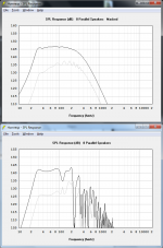
Pictures help a lot. This illustrates what I was trying to say.
First pic shows a single front loaded horn (light grey line) and a stack of 8 of the same horn (dark black line).
Second pic shows a single tapped horn (light grey line) and a stack of 8 of the same horn (dark black line).
In the tapped horn the dip caused by stacking multiple cabs isn't a big deal... unless it's in the usable passband.
Attachments
The only way to avoid off axis cancellation in the horizontal plane is to stack vertically (and use only one stack), but a vertical stack is not quite as efficient as a rectangular stack in terms of reflected ground plane frontal area, so may have slightly less VLF response.
It's also going to be very difficult to stack 8 three hundred pound cabs vertically in a 16 foot tall stack.
Hi just a guy,
Your example of "the dip" you described is the result of a compromise of the multiple speaker function in HornResp. The model used by HornResp to calculate the multiple speakers is based on the same model as two drivers in one large enclosure!
What that means is that in reality "the dip" in multiple coupled cabinets wouldn’t be that different from a single enclosure, if not better, just like weltersys showed you.
Another example;
16 foot tall arrays are quite easy to do using chain motors, but the chain motors need something to hang from.It's also going to be very difficult to stack 8 three hundred pound cabs vertically in a 16 foot tall stack.
The tallest I have stacked using human power only is 11.25 feet, about 3.5 meters.
Hi just a guy,
Your example of "the dip" you described is the result of a compromise of the multiple speaker function in HornResp. The model used by HornResp to calculate the multiple speakers is based on the same model as two drivers in one large enclosure!
I can't see how this would make any difference. I'm not a programmer and I don't know the math behind the Hornresp model but as far as I know, it only concerns itself with the axial path length and csa at points along that length, so one big box with multiple drivers or several small boxes is the same thing in the sim and in reality.
If what you are saying were true, it would be the same as saying if you took a tapped horn and added a solid line of bracing down the middle, all the way along the horn length, the response would be significantly different than if you didn't put bracing in. This doens't make any sense to me.
What that means is that in reality "the dip" in multiple coupled cabinets wouldn’t be that different from a single enclosure, if not better, just like weltersys showed you.
Another example;
The dip you are referring to in this pic is not the same dip I'm showing in my pic. In my pic, the first big peak shown in all tapped horn models turns into a big dip as more and more cabs are added.
In the pic you show that same peak is at 70 hz, and as you can see, as more cabs are added that peak starts to go away. Same as I showed (but in your pic the peak turns into a little pimple instead of a huge hole.)
The dip you are referring to at 120 hz in your pic is way higher in frequency than the first big peak I'm referring to, it correlates to the big dip at 220 hz in my pic. It doesn't matter much if that dip fills in or not, it's always going to be outside the usable pass band.
To be more clear about which peaks and dips are which, consider this. All tapped horn sims will show the first really big spiky peak (at 70 hz in your pic and 110 hz in my pic), then there will be another double peak a bit higher (at 90 and 100 hz in your pic and at 190 and 200 hz in my pic) and then there will be a big dip right above that (at 120 hz in your pic and 220 hz in my pic).
What I'm showing is a big peak in the middle of the passband turning into a big hole when multiple cabs are added, what you are showing is a big hole outside the passband being filled in as multiple cabs are added. Two very different things. And you example shows the same thing mine did but to a much lesser extent.
I've never simulated the th115 and I certainly don't have four of them to measure, but from your pic it would seem that the DSL horn is much more effective at constraining this problem (multiple cabs = big dip) than the simulation I showed. This doesn't come as a big surprise though, since I'm sure the impedance is very different (even though they cover a very similar bandwidth) and I chose the example that I did specifically because it highlighted the problem very well. So I'm not saying it will always be a problem with every design, but if you want to avoid this problem you have to plan for it ahead of time, which is very similar to the whole theme of this conversation.
Last edited:
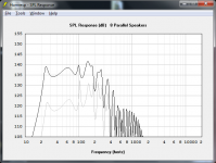
Here's another pic. This design is much closer to the way DSL designs tapped horns, and much less like the way the typical DIY'er designs tapped horns.
The light grey line is a single tapped horn, the darker black line is a stack of 8 of the same horns.
As you can see, this one doesn't have the big hole in response as multiple cabs are added but the peak at 100 hz is still greatly reduced even in this design. This proves that the problem is not Hornresp, the problem is the design. And since most people don't design like Danley does, picking a random tapped horn design off the internet and stacking it in multiples isn't the best choice.
(You might argue that this response doesn't look like Danley's measured results, especially the peak at tuning, but if you add some stuffing to the throat and mouth areas this would measure with the exact same response curve shape as the TH-Spud and DTS-10.)
Attachments
Last edited:
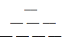
The light grey line is not a simulation of a stack of 8 horns, it is a simulation of one circular exit of 8 times the area as one simulated cabinet.The light grey line is a single tapped horn, the darker black line is a stack of 8 of the same horns.
To come close to that in half space, a stack of 8 would look something like the diagram below.
And the TH would have to have the entire frontal area as an exit.
I have not seen that type of TH or stack in the real world.
Attachments
- Status
- Not open for further replies.
- Home
- Loudspeakers
- Subwoofers
- Difference between Super Scoop and Folded Horn Subwoofers