Hello Edmond,
Today I tried to characterize my notch filter with the latest version of DiAna, but have had no success.
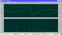
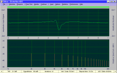
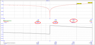
I followed the procedure laid out by you, and at the end of the procedure I obtained the plots shown in the first attachment, but the filter response file contains meaningless gain & phase angle values.
Since I'm always using this filter together with a 60dB LNA, this was also the combination I tested with DiAna. There were no overloads or any other problems with the signals in the course of the test.
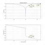
I've been using this filter for more than two years now, and its performance has been verified. The transfer function in the attachment was obtained by exciting the filter with band-limited white noise, recording a long data set of the excitation and response signals, and using Matlab to determine the transfer function. The agreement between the measurement and the theoretical response, i.e. LtSpice, is very good, so I'm confident that the filter is OK. Note that the phase angle in my filter freq. response plot uses a different convention from LtSpice, but adding 360 deg. to the phase angle curve results in the same values as obtained in LtSpice.
Since I have the filter transfer function coefficients, I'm able to easily generate the filter response file for DiAna as exemplified by the code segment you enclosed.
I'll be glad to provide any other information you may be interested in.
Regards,
Braca
Today I tried to characterize my notch filter with the latest version of DiAna, but have had no success.
I followed the procedure laid out by you, and at the end of the procedure I obtained the plots shown in the first attachment, but the filter response file contains meaningless gain & phase angle values.
Since I'm always using this filter together with a 60dB LNA, this was also the combination I tested with DiAna. There were no overloads or any other problems with the signals in the course of the test.
I've been using this filter for more than two years now, and its performance has been verified. The transfer function in the attachment was obtained by exciting the filter with band-limited white noise, recording a long data set of the excitation and response signals, and using Matlab to determine the transfer function. The agreement between the measurement and the theoretical response, i.e. LtSpice, is very good, so I'm confident that the filter is OK. Note that the phase angle in my filter freq. response plot uses a different convention from LtSpice, but adding 360 deg. to the phase angle curve results in the same values as obtained in LtSpice.
Since I have the filter transfer function coefficients, I'm able to easily generate the filter response file for DiAna as exemplified by the code segment you enclosed.
I'll be glad to provide any other information you may be interested in.
Regards,
Braca
Attachments
Hi Braca,
At the same sampling rate (48kHz, rather low btw!) I got the (about) same waveforms and harmonics. Also, I couldn't find any discrepancy between the response file data, measured response and simulated response. So therefore, could you show the first 10 lines (or so) of the response file, please?
Cheers, E.
Last edited:
Hello Edmond,
Yes, I've been wondering myself - with the graph very similar to yours, I was expecting to see at least a general notch filter characteristics.
Re. the sampling rate, if I'm measuring at 1kHz I'm content with seeing at least twenty harmonics. But if DiAna requires a higher sampling rate, I can go to 96kHz - that's where my audio interface ends.
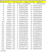
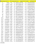
I'm enclosing the entire notch filter file for you to have a look at.
Regards,
Braca
Yes, I've been wondering myself - with the graph very similar to yours, I was expecting to see at least a general notch filter characteristics.
Re. the sampling rate, if I'm measuring at 1kHz I'm content with seeing at least twenty harmonics. But if DiAna requires a higher sampling rate, I can go to 96kHz - that's where my audio interface ends.
I'm enclosing the entire notch filter file for you to have a look at.
Regards,
Braca
Attachments
Hi Braca,
Indeed, the notch file shows rubbish. Only harmonic serial numbers and frequency are correct. Gain and phase looks really weird. So I'm at least as puzzled as you are.
As for a sampling rate (SR) of 48kHz, that should not give any problems.
According to post 781, channel B is the reference (unnotched) channel, right?
So the notch filter is connected to channel A. How does this channel look like?
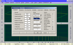
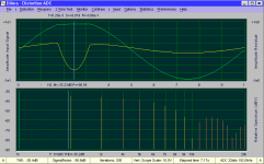
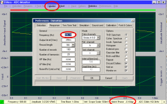
Below you see my settings, ref-channel, test-channel and file output, obtained at SR=48kHz.
Except the file data, how does it compare with your results?
Cheers, E.
PS: I hardly dare to ask, but are you sure the fundamental frequency equals the notch frequency of the filter itself?
Indeed, the notch file shows rubbish. Only harmonic serial numbers and frequency are correct. Gain and phase looks really weird. So I'm at least as puzzled as you are.
As for a sampling rate (SR) of 48kHz, that should not give any problems.
According to post 781, channel B is the reference (unnotched) channel, right?
So the notch filter is connected to channel A. How does this channel look like?
Below you see my settings, ref-channel, test-channel and file output, obtained at SR=48kHz.
Except the file data, how does it compare with your results?
Cheers, E.
PS: I hardly dare to ask, but are you sure the fundamental frequency equals the notch frequency of the filter itself?
Attachments
bug
@Braca,
At least I've discovered one (minor) flaw. The gain and phase of the output file (in post 784) are inverted, respectively negated. This happens when the wrong reference channel is selected. However, it also happens when at first the wrong reference channel was selected (and used) and thereafter the correct reference channel is selected, without checking off again 'Characterize notch filter' in the Option menu.
Although this flaw seems unrelated to the errors you got, I have to correct this bug first and then investigate why you get such weird results.
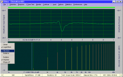
Below you see the correct notch filter output:
BTW, do you like an automatic conversion from degrees to radians? For example by looking at the largest phase angle and when it exceeds say 10 rads, then, apparently, the phase was expressed in degrees instead of radians.
Cheers, E.
@Braca,
At least I've discovered one (minor) flaw. The gain and phase of the output file (in post 784) are inverted, respectively negated. This happens when the wrong reference channel is selected. However, it also happens when at first the wrong reference channel was selected (and used) and thereafter the correct reference channel is selected, without checking off again 'Characterize notch filter' in the Option menu.
Although this flaw seems unrelated to the errors you got, I have to correct this bug first and then investigate why you get such weird results.
Below you see the correct notch filter output:
BTW, do you like an automatic conversion from degrees to radians? For example by looking at the largest phase angle and when it exceeds say 10 rads, then, apparently, the phase was expressed in degrees instead of radians.
Cheers, E.
Attachments
Edmond, I found the error in my system - it had something to do with my LNA.
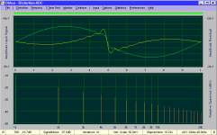
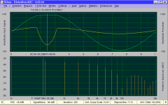
Characterizing my notch filter in DiAna alone, i.e. without the LNA in series, produces the gain vs. frequency curve as in the attachment.
It worries me that the gain at the 2nd and 3rd harmonics does not agree with the theory and my previous measurements by almost 10dB. The relative gain difference between these two points is approx. 6dB in DiAna vs. 4dB previously.
The filter insertion loss appears to be correct at about 2dB.
I also noticed that there seems to be interaction between the channel settings in the "Calibration" and "Distortion" tabs. When I set "A" in the "Calibration" tab and "B" as the Test channel in the "Distortion" tab, I get THD in the channel "A", although "A" is the Reference channel in this case.
The same happens when the channels are reversed, i.e. "B" in the "Calibration" and "A" as the Test channel in "Distortion".
Hope this input is useful.
Regards,
Braca
Attachments

Hi Braca
BTW, what do you mean by "previously"? The first time DiAna said 4dB and now suddenly 6dB?
Anyhow, I've no explanation for this discrepancy.
Regarding the notch filter characterization, you may also have a look at channel H. This represent the final data as output to the file. Note the options by clicking on the lower left pane with the right mouse button. You also can adjust the scale with the up- and down cursor keys in combination with the Ctrl or Shift key.
Cheers, E.
PS: What "LNA" stands for, just Low Noise Amplifier?
I'm glad you found the cause of that error.Edmond, I found the error in my system - it had something to do with my LNA.
Hmm.. that's rather peculiar, because I get just a 4dB difference as it should be (see also the pic. below).Characterizing my notch filter in DiAna alone, i.e. without the LNA in series, produces the gain vs. frequency curve as in the attachment.
It worries me that the gain at the 2nd and 3rd harmonics does not agree with the theory and my previous measurements by almost 10dB. The relative gain difference between these two points is approx. 6dB in DiAna vs. 4dB previously.
The filter insertion loss appears to be correct at about 2dB.
BTW, what do you mean by "previously"? The first time DiAna said 4dB and now suddenly 6dB?
Anyhow, I've no explanation for this discrepancy.
Regarding that interaction, I've noticed that too and made a note in my to-do list. But for the moment, I'm afraid you have to live with it, if you don't mind (if Diana refuses to switch to the other channel, it helps when toggling a few times between A and B).I also noticed that there seems to be interaction between the channel settings in the "Calibration" and "Distortion" tabs. When I set "A" in the "Calibration" tab and "B" as the Test channel in the "Distortion" tab, I get THD in the channel "A", although "A" is the Reference channel in this case.
The same happens when the channels are reversed, i.e. "B" in the "Calibration" and "A" as the Test channel in "Distortion".
Hope this input is useful.
Regards,
Braca
Regarding the notch filter characterization, you may also have a look at channel H. This represent the final data as output to the file. Note the options by clicking on the lower left pane with the right mouse button. You also can adjust the scale with the up- and down cursor keys in combination with the Ctrl or Shift key.
Cheers, E.
PS: What "LNA" stands for, just Low Noise Amplifier?
Attachments
Hello Edmond,
Thank you for the detailed reply.
In my comparing the difference between the H2 and H3 being 6 and 4dB, "previous" refers to my measurements and theory.
You're right about the term LNA. I've got two, one after S. Wurcer, and another one from S. Groner (Linear Audio Vol. 3).
BTW, I don't have the channel H in my copy of DiAna - clicking the lower left corner displays channels A and B only.
Regards,
Braca
Channels beyond B
Just press H on your keyboard.
Cheers, E.
PS: Do you also get a 6dB difference between the H2 and H3 when SR=96kHz?
Channel H is only meant for privileged users. 😉Hello Edmond,
[...]
BTW, I don't have the channel H in my copy of DiAna - clicking the lower left corner displays channels A and B only.
Regards,
Braca
Just press H on your keyboard.
Cheers, E.
PS: Do you also get a 6dB difference between the H2 and H3 when SR=96kHz?
Last edited:
Thanks for the tip!
I've just ran a test at 96kHz - the gain difference between H2 and H3 remained 6dB.
I've just ran a test at 96kHz - the gain difference between H2 and H3 remained 6dB.
You're welcome.Thanks for the tip!
I've just ran a test at 96kHz - the gain difference between H2 and H3 remained 6dB.
 🙁
🙁Also in channel H?
Is there any possibility that some other filter is involved?
What do you get if you connect the notch filter to the other channel (and set the Ref. channel accordingly, of course)?
And as a last resort, could you drop the schematic of the notch filter?
Cheers, E.
Yes, the difference between H2 and H3 is the same on the H-page.
I've characterized the notch filter always in the same manner: first on channel A, then connected it on channel B, changed the ref. channel, pressed "Continue", and saved the filter.
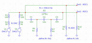
My notch filter is based on the so-called Hall topology, and the PCB design comes from Samuel Groner. There was a GB for his PCB on this forum:
PCB for Samuel Groner's low distortion passive notch filter
I wrote a couple of posts on this thread.
I made an adjustable version of this filter for 1kHz ±10Hz because I almost always use a high-performance, fixed-frequency oscillator instead of the DAC in my audio interface.
As already mentioned, I measured the filter transfer function and it agrees very well with LtSpice.
Just to make sure, I'll measure the filter gain at 2 and 3kHz using a signal generator, and report the results.
Regards,
Braca
I've characterized the notch filter always in the same manner: first on channel A, then connected it on channel B, changed the ref. channel, pressed "Continue", and saved the filter.
My notch filter is based on the so-called Hall topology, and the PCB design comes from Samuel Groner. There was a GB for his PCB on this forum:
PCB for Samuel Groner's low distortion passive notch filter
I wrote a couple of posts on this thread.
I made an adjustable version of this filter for 1kHz ±10Hz because I almost always use a high-performance, fixed-frequency oscillator instead of the DAC in my audio interface.
As already mentioned, I measured the filter transfer function and it agrees very well with LtSpice.
Just to make sure, I'll measure the filter gain at 2 and 3kHz using a signal generator, and report the results.
Regards,
Braca
Notch filter response
Hi Braca,
Thanks for the info. I've simulated Samuel's filter and I also got a difference of 4dB between H2 and H3. But.... when I loaded this filter with 3kOhm (at the output) it increased to that unexpected 6dB. So maybe the input impedance of your ADC is just a little too low. What sound card do you have?
Cheers, E.
Version 1.54.11
Thesethree features/flaws two flaws have been addressed in version 1.54.11, which can be downloaded from my website (PW=Yohimbine).
Cheers, E.
At least I've discovered one (minor) flaw. The gain and phase of the output file (in post 784) are inverted, respectively negated. This happens when the wrong reference channel is selected. However, it also happens when at first the wrong reference channel was selected (and used) and thereafter the correct reference channel is selected, without checking off again 'Characterize notch filter' in the Option menu.
[...]BTW, do you like an automatic conversion from degrees to radians? For example by looking at the largest phase angle and when it exceeds say 10 rads, then, apparently, the phase was expressed in degrees instead of radians. [then all phases will be converted to degrees]
Cheers, E.
[..]
I also noticed that there seems to be interaction between the channel settings in the "Calibration" and "Distortion" tabs. [...]
Regards,
Braca
These
Cheers, E.
Last edited:
Reconstruction of "notched" signals
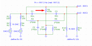
During characterizing the notch filter, it's also important to ensure that the reference channel sees the notch filter input signal, instead of the DAC output of some other channel or so, again see fig.1
@Braca,
Regarding the issues you have experienced, I'm pretty sure it's hardware related, because we are using the same software. Maybe you could could characterize the notch filter again, but now the filter connected as shown in fig1.
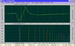
Then generate a heavily distorted signal, that is, a distortion well above the noise level. The easiest way is to simply overload the DAC (without overloading the ADC, of course). In the example below I've also added an offset to make the distortion asymmetrical, otherwise the even harmonics are too low for a meaningful reconstruction (of those harmonics).
Fig.2 the signal before the notch filter.
Fig.3 the signal after the notch filter.
Fig.4 the signal after enabling the Apply notch compensation in the Option menu.
Fig.2 and fig.4 are identical, except the top of the input signal, which shows a tiny difference : S=+9.0919 vs S=+9.018, an error of only 1mV. Also the harmonics are virtually identical.
Anyhow, this proves that all this notch filter stuff is working properly. If you don't get identical results, I can only conclude that something else must be wrong, but what?
Cheers, E.
Very true, in particular with respect to attenuation of the fundamental itself (far less regarding harmonics). This makes the reconstruction of the input signal as present before the notch filter very critical. A one day old notch data file, for example, easily results in an error of 1dB. In order to make it less critical, I've spoiled the notch filter a little by reducing the notch to -60dB from -80dB, see fig.1, R6.[..]
And regarding the notch filter, the attenuation is varying with temperature, i have built several of them. So it´s very important to measure the fundamental signal before and after the twin T notch filter.
During characterizing the notch filter, it's also important to ensure that the reference channel sees the notch filter input signal, instead of the DAC output of some other channel or so, again see fig.1
@Braca,
Regarding the issues you have experienced, I'm pretty sure it's hardware related, because we are using the same software. Maybe you could could characterize the notch filter again, but now the filter connected as shown in fig1.
Then generate a heavily distorted signal, that is, a distortion well above the noise level. The easiest way is to simply overload the DAC (without overloading the ADC, of course). In the example below I've also added an offset to make the distortion asymmetrical, otherwise the even harmonics are too low for a meaningful reconstruction (of those harmonics).
Fig.2 the signal before the notch filter.
Fig.3 the signal after the notch filter.
Fig.4 the signal after enabling the Apply notch compensation in the Option menu.
Fig.2 and fig.4 are identical, except the top of the input signal, which shows a tiny difference : S=+9.0919 vs S=+9.018, an error of only 1mV. Also the harmonics are virtually identical.
Anyhow, this proves that all this notch filter stuff is working properly. If you don't get identical results, I can only conclude that something else must be wrong, but what?
Cheers, E.
Attachments
Hello Edmond,
I only now got some time to have a look at the recent posts; I'm grateful for your support and the new version of DiAna.
While you're right that a low impedance at the sound card's input affects the attenuation of the harmonics, I don't believe that my sound card (MOTU Audio Express) has an input impedance below, say 10K. MOTU do not quote these data (they only quote the input sensitivity).
My white noise measurement of the transfer function returned an agreement better than 1dB with the theory, so I remain without a clue as to the possible cause of the disagreement with DiAna.
In any case, I hardly ever use the notch filter directly connected to the sound card, i.e. there is always an LNA after the filter when I'm measuring THD. The fundamental rejection itself does not matter very much - as long as it's better than -40dB - but the accuracy of the gain at the harmonics is of utmost importance. This is why I'm going to concentrate on measuring the filter together with the LNA. In this way I won't have to manually compensate for the post-filter gain when evaluating THD, and it should also afford a better accuracy when characterizing the filter because the ADC is then operating at levels that are 60dB higher than in the case of the filter alone.
So there is work to do - I'll report back when there are new results.
Regards,
Braca
Nevertheless, I should measure it. Better safe than sorry.Hello Edmond, [...]
I don't believe that my sound card (MOTU Audio Express) has an input impedance below, say 10K. MOTU do not quote these data (they only quote the input sensitivity).
NB: With an load of 10kOhm, the H2-H3 difference is 5.4dB, almost as large as that pesky 6dB ! (simmed with MicroCapV10) See pictures below. So I think we are on the right track.
May I ask how much accuracy do you need? 1dB, 0.1dB 0.01dB?[...]
The fundamental rejection itself does not matter very much - as long as it's better than -40dB - but the accuracy of the gain at the harmonics is of utmost importance.
Agreed, but during error search, I would exclude the LNA. The less components involved, the easier the error search.This is why I'm going to concentrate on measuring the filter together with the LNA. In this way I won't have to manually compensate for the post-filter gain when evaluating THD, and it should also afford a better accuracy when characterizing the filter because the ADC is then operating at levels that are 60dB higher than in the case of the filter alone.[...]
Regards,
Braca
Also, with an additional gain of 60dB, beware of overloading the LNA and ADC, because the harmonics are much higher than under normal conditions. H2, for example, is -20dB WRT the fundamental.
Anyhow, I hope you will find the culprit. Good luck.
Cheers, E.
Attachments
I stand corrected as to my expectation for the line input impedance of my audio interface being more than 10K - it is 5K (measured)!
So Edmond has been on the right track all the time.
The reason for the good agreement between my LtSpice simulation and the measured transfer function is that I used the high-Z input of the interface for the measurement (I found my notes🙂), and the simulation was done with a load of 1M.
Regards,
Braca
V1.54.12
Hi Braca,
I'm glad you found the culprit. Well done!
I the meantime I've made a new version (1.54.12) that shows the phase difference between the test channel and the reference channel. This way it's much easier to enter the exact notch frequency. Just select 'Characterize notch filter' option, open the Distortion menu and click on the Monitor button. Now the phase is displayed on the status bar.You can change the frequency 'on the fly' in order the minimize the phase (see picture).
Regarding the notch file, if you prefer, you may also enter the phase angles expressed in degrees (see also post 794).
Cheers, E.
Attachments
Version 1.54.13 uploaded
The previous version was a little unstable when entering wildly different frequencies on the fly (see post 799). Switching from 1kHz to 2kHz, for example, was okay, while switching from 1kHz to 50kHz, the program went haywire. I've fixed it together with a few other minor tweaks.
Cheers, E.
The previous version was a little unstable when entering wildly different frequencies on the fly (see post 799). Switching from 1kHz to 2kHz, for example, was okay, while switching from 1kHz to 50kHz, the program went haywire. I've fixed it together with a few other minor tweaks.
Cheers, E.
- Home
- Design & Build
- Equipment & Tools
- DiAna, a software Distortion Analyzer