virus
Regarding virus warnings, I've installed the latest version of Security Essentials for windows 7 32 bits. This version has no issues with DiAna. Dito with NOD32 and MS defender. 🙂
Regarding virus warnings, I've installed the latest version of Security Essentials for windows 7 32 bits. This version has no issues with DiAna. Dito with NOD32 and MS defender. 🙂
Last edited:
I tried on Windows XP-32bit and follow the steps of link DiAna
Unfortunately, just I press the Distortion button "Click on the 'Distortion' button to start the ADC", I have "error ADC not initilalized, error code 108".
I deleted the configuration file and tried from begging but I have the same error again!
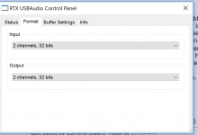
On preferences I have the EMU0404.
Any suggestion?
Unfortunately, just I press the Distortion button "Click on the 'Distortion' button to start the ADC", I have "error ADC not initilalized, error code 108".
I deleted the configuration file and tried from begging but I have the same error again!
On preferences I have the EMU0404.
Any suggestion?
Attachments
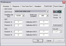
@lemon, What are the following values in the ini file for: NoADC, SampleRate and AsioBufLen? If NoADC is non zero or SampleRate is zero or AsioBufLen is zero, you will get this error msg.
Did you hit the control panel button?
PS: The sound card preference page looks OK.
Did you hit the control panel button?
PS: The sound card preference page looks OK.
Last edited:
Hi David,
No, I've not tried that. But why I should do it? Doesn't it burn a lot of extra CPU cycles? First, there is the Hilbert x-form itself, then a complex FFT, which takes twice as much time as an FHT (remember, DiAna has to do FHT's in real time and an awful lot of other computations like software discriminators etc.).
Cheers, E.
PS: In the past I've played with hardware Hilbert transformers, that is, a polyphase network for generating and receiving SSB signals and decoding quadraphonic LP records. 🙂
No reason to use it.
Mainly I'm learning a new language, c#. So I'll try anything.
With the GC in c# memory resources are not as big an issue. As for the CPU, get a bigger one.
@lemon, What are the following values in the ini file for: NoADC, SampleRate and AsioBufLen? If NoADC is non zero or SampleRate is zero or AsioBufLen is zero, you will get this error msg.
edit: Did you hit the control panel button?
The sound card preference page looks okay.
edit: Did you hit the control panel button?
The sound card preference page looks okay.
Last edited:
No reason to use it.
Mainly I'm learning a new language, c#. So I'll try anything.
With the GC in c# memory resources are not as big an issue. As for the CPU, get a bigger one.
Indeed. memory isn't a big issue, but not everybody have an Intel core i7 7820X, so CPU load might get an issue. When Diana runs in differential mode, it also has to synthesize a precisely defined and bandwidth limited sawtooth and that alone burns a lot of CPU cycles. BTW, I'm still programming in good old plain C and using a compiler from Walter Bright (a very bright guy). Maybe, in the future, I'll switch to the D (from the same guy). Way more elegant and logical than C.
Hi kannan,
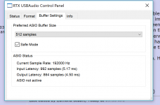
I'm afraid the ASIO control panel (ACP) is making troubles again. <snip>
Cheers, E.
edit: Could you upload a picture of the ACP?
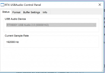
here it is - pictures and ini
Code:
[PRM]
CmdShow=1
ScreenRatio=0.5
Left=375
Top=250
Right=1125
Bottom=750
HorBdrHig=4
VerBdrWid=12
PropPosX=-0.000666666
PropPosY=0
BoxPosX=0
BoxPosY=0
PrintPosX=0
PrintPosY=0
FilePosX=0
FilePosY=0
ChildPage=0
ChildSizeX=0
ChildSizeY=0
ChildPosX=0
ChildPosY=0
AsioPosX=0
AsioPosY=0
PrefStart=0
RunMode=0
DataMode=2103
Channel=0
Ref=0
NoADC=1
LinLogX=941
LinLogY=922
AbsRel=924
DriftComp=00000000
noCRCwarning=0
GraphicModes=00000009
Spare=0
StepTime=0
PrintColor=0
FhtMode=00000007
FhtThldCoher=14
FhtThldIncor=6
CpuLoadThld=15
NumSyntThrds=3
BugRep=1
DataDir=C:\Users\kannan\Downloads\Diana-demo\
OutFileName=C:\Users\kannan\Downloads\Diana-demo\ss.wav
CRC=14467
[DPB]
Frequency=4997
Amplitude=0.25
LowPassFilter=100000
NoiseFilter=0
ScopeGain=1
TriggerLevel=0
TimeBase=0.001
FilterMode=345
TriggerSlope=936
IdxRecLen=3
RecLen=4096
RecNum=100
SyncMode=341
InterpolMode=3
NumHarm=20
Repeat=0
Grid=1
Monitor=5
ApoTol=1E-18
FapoTol=1E-17
OutlierTol=0.01
NoiseMargin=0.0001
Degrees=927
Channels=3
IntervalTime=500
DeadTime=10
LastAmpli=0
DelStpDelAmp=1000
MaxSawtHarms=256
SpecHist=350
DialogueID=360
CRC=41288
[SPB]
Frequency=0
AmpDrift=0
OffsetDrift=0
FreqDrift=0
Noise=NAN
DC Offset=0
Xover=0
Resol=0
Harmonic1=0
Harmonic2=0
Harmonic3=0
Harmonic4=0
Harmonic5=0
Harmonic6=0
Harmonic7=0
Harmonic8=0
Harmonic9=0
Harmonic10=0
Phase1=0
Phase2=0
Phase3=0
Phase4=0
Phase5=0
Phase6=0
Phase7=0
Phase8=0
Phase9=0
Phase10=0
Options=0
DialogueID=0
CRC=31661
[APB]
AsioDriverName=RTX ASIO Driver
ASIOdriverNumber=0
MaxInputChannels=2
MaxOutputChannels=2
CurInputChannels=2
CurOutputChannels=2
ADC1Channel=1
ADC2Channel=2
DAC1Channel=1
DAC2Channel=2
AsioDataType=18
AsioBufLen=0
AsioMinLen=0
AsioMaxLen=0
AsioPrefLen=0
AsioGrany=0
SampleRate=192000
SoftStart=1
Monitor=5
TimeBasee=0.001
ScopeGain=1
ComPort=1
DialogueID=0
CRC=55547
[CPB]
Height=-11
Width=0
Escapement=0
Orientation=0
Weight=400
Italic=0
Underline=0
StrikeOut=0
CharSet=0
OutPrecision=1
ClipPrecision=2
Quality=1
PitchAndFamily=0
FaceName=Arial
LineThickness=1
ItemClr1=00400000
ItemClr2=00DEFFFF
ItemClr3=002D2D00
ItemClr4=00E6AAB4
ItemClr5=00008000
ItemClr6=00DCC878
ItemClr7=00FFFFFF
ItemClr8=0000A0FF
ItemClr9=0040FF00
ItemClr10=0000FFFF
ItemClr11=00FA9696
ItemClr12=004080FF
ItemClr13=00FF0000
ItemClr14=0040FF00
ItemClr15=0000FFFF
ItemClr16=004080FF
ItemClr17=0000FFFF
ItemClr18=00FF3434
ItemClr19=00BEBEBE
ItemClr20=0000FF00
ItemClr21=0000DE00
ItemClr22=000000FF
CustClr1=00FFFFFF
CustClr2=00EFEFEF
CustClr3=00DFDFDF
CustClr4=00CFCFCF
CustClr5=00BFBFBF
CustClr6=00AFAFAF
CustClr7=009F9F9F
CustClr8=008F8F8F
CustClr9=007F7F7F
CustClr10=006F6F6F
CustClr11=005F5F5F
CustClr12=004F4F4F
CustClr13=003F3F3F
CustClr14=002F2F2F
CustClr15=001F1F1F
CustClr16=000F0F0F
CustClr17=00000001
CustClr18=00000000
CustClr19=00000000
CustClr20=00000000
CustClr21=00000000
CustClr22=00000000
DialogueID=0
CRC=41912
Attachments
You can download the Asio driver from ATX site
If these can be updated manually to make it work - might try
AsioBufLen=0
AsioMinLen=0
AsioMaxLen=0
AsioPrefLen=0
AsioGrany=0
Other parameters seem ok among your list
If these can be updated manually to make it work - might try
AsioBufLen=0
AsioMinLen=0
AsioMaxLen=0
AsioPrefLen=0
AsioGrany=0
Other parameters seem ok among your list
Windows only, looks like a virus, and closed source. I am out.
It's definitely not a virus, it's a false positive. You better use a more decent virus scanner or switch off that silly thing.
Great ! How you did it? Did you modify the ini file manually?Yes all had wrong values (NoADC=-2, SampleRate=0, AsioBufLen=0)
Now, it is working.
I suppose it works, but you have to supply the correct figures by yourself.The calibration works? I didn't at Preferences Menu.
Do you know the full scale voltages of the ADC and DAC?
I changed manually the NoADC=0 and SampleRate=48000 and run the DiAna.
I took an error that I did't note, close the program, run again and works (choose the Replace...something in memory).
I don't know if the following method is good but I have done these steps for the input calibration.
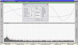
I set the Output Level to 1 (what is that finally, rms, average or peak to peak).
Run the generator pressing the distortion, I set the volume EMU output until to read 1Vrms at EMU input.
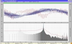
Finally, the DiAna gives -11.66dB the level of basic frequency that it is very closed to the real value, I think.
I took an error that I did't note, close the program, run again and works (choose the Replace...something in memory).
I don't know if the following method is good but I have done these steps for the input calibration.
I set the Output Level to 1 (what is that finally, rms, average or peak to peak).
Run the generator pressing the distortion, I set the volume EMU output until to read 1Vrms at EMU input.
Finally, the DiAna gives -11.66dB the level of basic frequency that it is very closed to the real value, I think.
Attachments
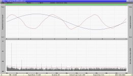
With a calibration factor of just 1 , the "voltages" as shown are no real voltages, instead, they are fractions of the full scale value.From what I saw, at the Preferences->Distortion, the Output Level is the gen. output level in Vpp.
At my capture this set to 800mVpp, but when read distortion the Amplitude is 0.23V, how are these correlated?
Is that way to adapt the FFT values?
So, during capture 800mVp (it's not mVpp) means that the DAC peak signal is 0.8 of full scale (FS). At the same time this signal is fed to the ADC, but apparently the FS voltage is about three time higher, more precisely 0.8/0.23= 3.478 times higher. That's weird, as the specs of the emu card say that the levels of both line input and line output are +12dB. Is there perhaps a mixer with faders who aren't put in the highest position?
As for the calibration procedure:
Suppose that the full scale input voltage of the ADC is 5.0V, then put 5.0 in the corresponding edit box of the preference audio page.
Regarding the DAC, it's the other way around: suppose the DAC full scale output voltage is 2.5V, then put 1/2.5=0.4 in the corresponding edit box of the preference audio page (why the division in case of the DAC? Because in both cases (ADC and DAC) the calibration factors are used as multipliers).
Note: You need a reliable AC voltmeter for the calibration.
Cheers, E.
Last edited:
Windows only, looks like a virus, and closed source. I am out.
No, it isn't virus.
I have the AVG protection on my lab PC, the first time that run the program the AVG pop-up a menu that scans this for viruses e.t.c
It passes the scan 100% with success.
With a calibration factor of just 1 , the "voltages" as shown are no real voltages, instead, they are fractions of the full scale value...
- So, it is a FS Indicator of gen. output. Maybe, for the user is more simple to have an indication area with 0,-1,-2dB and so on with text like "Generator Output (dBFS)"
As for the calibration procedure:
Suppose that the full scale input voltage of the ADC is 5.0V, then put 5.0 in the corresponding edit box of the preference audio page.
- That means in example, Preferences->Sound Card, "Calibration ADC1/ADC2 = 5.0"
Regarding the DAC, it's the other way around: suppose the DAC full scale output voltage is 2.5V, then put 1/2.5=0.4 in the corresponding edit box of the preference audio page (why the division in case of the DAC? Because in both cases (ADC and DAC) the calibration factors are used as multipliers).
- That means in example, Preferences->Sound Card, "Calibration DAC1/DAC2 = 0.4" when the Preferences->Distortion, Output Level=1
Note: You need a reliable AC voltmeter for the calibration.
- Always, the true-RMS voltmeter is around at the lab!
Thanks a lot for the help.
Posts 55, 57 is the answer.
Before this, I followed a practical way (post54) but it isn't the 100% the right way.
Before this, I followed a practical way (post54) but it isn't the 100% the right way.
"- Always, the true-RMS voltmeter is around at the lab!"
Remember to multiply the results by sqrt(2), as you need the peak values.
Remember to multiply the results by sqrt(2), as you need the peak values.
- Home
- Design & Build
- Equipment & Tools
- DiAna, a software Distortion Analyzer