Hi @anatech
Thank you for your wishes. I have to work hard on my design, but now the way is almost clear.
None of my preamps uses a feedback loop. It seems absurd to me to introduce an error and then have to correct it after it has occurred. I should say "while it occurs", which sometimes is true, and when it is, you see you don't need any feedback loop.
I certainly don't want to use feedback to widen an insufficient bandwidth.
My goal is good sound which is not necessarily dependent on ultra-low distortion. I never aimed to achieve the lowest % of distortion with lots of zeroes to show.
On the other hand, a well-conceived main amp benefits from feedback on the damping factor which corrects the speakers' errors while they occur.
I still think using multiple final pairs will lead to a decent damping factor, I have to think about it, perhaps I would use the feedback also in this case, but the VAS must be able to work open loop, before applying the feedback.
Many amplifiers claiming not to use global feedback do use some local loops instead, like around the output stage. If you call it “error correction” it may not count as feedback, despite it is.
Small signal amplification can be made so inherently linear that feedback is not required to achieve low distortion.
Multiple power transistors are an excellent idea. With many transistors in parallel, output impedance can be pretty low indeed.
Small signal amplification can be made so inherently linear that feedback is not required to achieve low distortion.
Multiple power transistors are an excellent idea. With many transistors in parallel, output impedance can be pretty low indeed.
I saw yoy checked the link at my post #37, The Audio Amp.
The final stage is a DTB with 17db gain using feedback within each triplet branch. I don't know how to evaluate it (if the triplets' open loop band goes over the audio band or it doesn't), but it is interesting. I'm forcing myself to ignore it. My friend who bought this amp likes its sound a lot.
I'm trying to understand if the mu-follower I have in mind will be able to drive a 200W DTB (the straight one). It needs a near 60V peak to give 200Wrms. This problem doesn't exist with the DTB in "The Audio Amp".
Interestingly enough, the best is an amp designed to be very linear, then wrapped in negative feedback.
Any thoughts of time delay are only made by people who don't understand just how fast the signal travels. There is no possibility of "zero instantaneous feedback" anywhere near the audio range unless you clip. This creates massive distortion, feedback or no. You only get "sticking" if the circuit isn't designed well.
Negative feedback around a good circuit is a very good thing. It makes a good thing even better. However, there is nothing wrong with designing without negative feedback. But don't avoid it because you think it is "evil".
marigno, excellent you're having success.

Thank you for encouraging me!
I feel unsure of what to do.
To drive a 200W DTB a 60V signal is needed, and can not be obtained from a single-stage VAS, certainly not a mu-follower which shows a lower swing. Good as a preamp, not as a VAS.
Before deepening the DTB project, I need to focus on a VAS that can accomplish the required 60Vp.
I have lots of twin triode tubes but not even one single triode. Since a cyclotron buffer is also on the way (in my mind only by now), I thought it would be nice to build a VAS that can give a two-phase signal. The DTB uses only one phase unless one thinks about a bridged DTB.
Recently I came across a tube main amp using the "shunt feedback", aka "Shade feedback". On that base, I was able to put together this VAS schematic.
I tried to remove C1 and C2 capacitors, but as a consequence, the gain of the second stage would be too low.
The gain of this VAS allows a feedback loop for a good DF.
Comments are very welcome!
Attachments
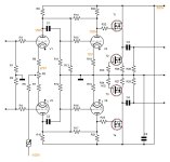
T3, T4 are incorrect in your drawing. I'm assuming capacitively coupled output because you can't use a bipolar supply with tubes like that.
Chase it, see where you get.
Chase it, see where you get.
I can't understand your answer. They are not bipolars, they are mosfets configuring a buffer. T1 (enhanced) is the same as T4, T2 (depletion) is the same as T3, and they are connected the same way, what is in the upper part is the same in the lower part.
So post #46 is two identical stages, and you intend to drive it with balanced, anti-phase inputs? (BTW, what is purpose of R13?) I don't understand how balanced drive outputs will help unless you plan to drive your speakers with two DTB buffers in bridge configuration. Is this the plan?
What if you used only the top half of that design (with R6 grounded instead of connecting to pot R9)? Would you elaborate what prevents the upper half of your design from delivering 120V pk-pk? Distortion?
If distortion is the problem, I suggest feedback. I assume your VAS needs voltage gain of about 30. Investigate bypassing R18 with a large cap to ensure large AC gain from V5. Connect a feedback resistor from cathode of V1 to source of T1 to set gain, added resistor being about 30 * R6. You might have to adjust grid voltage of V1. Is that at all promising?
Obviously, I'm a believer in feedback, and I whole heartedly endorse @anatech comments in post 45. IMHO, negative feedback and control loop theory ranks in importance with the inventions of the tube and the transistor. A different application, but consider Elon Musk/SpaceX recent feat. Whole lot of feedback loops in that astonishing accomplishment!
I have several comments to offer on your original DBT, including how to implement a well damped DC servo, if desired. But I agree with your desire to first settle on the overall approach. I think your approach is interesting and I encourage your pursuit!
Thank you for your suggestion.
In post 46 I wrote I have in mind also a Circlotron, which needs to be driven by a balanced signal. This is the reason the schematic is a balanced one.
Obviously, the DTB uses only one phase. Focusing on the DTB, the lower (or upper) half of the schematic can be erased.
R13 trims the feedback being placed between two high-impedance opposite phase points. But can be omitted.
I agree that setting up only the upper half of the schematic R6 can be put to the mass. A lot simpler, with no need for a negative power supply.
My problem is that I have a lot of twin triodes tubes, and the two stages, at first glance, need two different triodes, which prevents the employment of a single twin tube. I could also use triodes paralleled, I won't let the same tube manage two channels, all my recent builds are dual mono.
I'd not bypass R18, the gain should be enough, and it is better to have local feedback on V5 (my typo, it should be V3). Maybe a partial bypass can be the solution. The design uses the shunt feedback (aka Shade), so another feedback loop is not needed.
The gain of the VAS must be 60 (35.6db) to be able to obtain 56Vp at the output of the DTB with 1Vp at the input.
Your comments about the DTB will be very welcome, overall the ones about the servo.
Hi marigno,
T2 and T3 are depletion mode, the body diode in T3 will conduct heavily. T1 and T4 are enhancement mode. The body diode in T4 will conduct heavily. They are all indicated as N channel. You have two forward biased diodes from the midpoint (output) to common as you have drawn things.
So you must have a +300 VDC supply, single ended as indicated on your schematic, your mosfet stage need a negative rail as drawn. V1 and V2 appear to be a long tailed pair.
Yeah, R13 doesn't make sense to me either. It just loads the two plates for a differential signal. Probably not what you want.
No, I understand what they are. I was referring to the power supply, sorry I wasn't more clear.I can't understand your answer. They are not bipolars
T2 and T3 are depletion mode, the body diode in T3 will conduct heavily. T1 and T4 are enhancement mode. The body diode in T4 will conduct heavily. They are all indicated as N channel. You have two forward biased diodes from the midpoint (output) to common as you have drawn things.
So you must have a +300 VDC supply, single ended as indicated on your schematic, your mosfet stage need a negative rail as drawn. V1 and V2 appear to be a long tailed pair.
Yeah, R13 doesn't make sense to me either. It just loads the two plates for a differential signal. Probably not what you want.
@BSSTConnect a feedback resistor from cathode of V1 to source of T1 to set gain
Here is the single-phase VAS schematic good for the DTB.
A conventional feedback resistor cannot be connected as you suggested, it must be DC decoupled, look the blue R31.
@anatech
I really cannot see what you mean. The body diodes are polarized in reverse, they will not conduct. What happens in T3 the same happens in T2; similarly, what happens in T4 the same happens in T1. Why T1, T2 are safe and T3, T4 are not?
The negative rail of the power supply is connected to mass, which is connected to T3, T4 sources.
Attachments

I mean T
I mean T2, T3 sourcesThe negative rail of the power supply is connected to mass, which is connected to T3, T4 sources.
Hi marigno,
Ahhh, sorry. My brain is used to seeing bipolar power supplies like yours is drawn, not a positive one flipped over as yours is. You are quite right.
The diagram just isn't drawn as I normally see, that's all. Each output is loaded with a CCS to common.
Ahhh, sorry. My brain is used to seeing bipolar power supplies like yours is drawn, not a positive one flipped over as yours is. You are quite right.
The diagram just isn't drawn as I normally see, that's all. Each output is loaded with a CCS to common.
I need somebody so gentle to validate my schematic at post #46. It derives from the "Baby Huey" in this thread:
Let it be clear that it must supply a driving signal of at least 60Vp per phase with 1Vp at its input.
I will build it balanced because this is the shortest way for me to hear its sound. I will connect it as a front end to a cyclotron mid-power buffer back end I already have. Its present front end is a buffered DC coupled Concertina, Williamson style, which I wish to improve.
With the DTB I intend to build, only one phase will be used, and its design is now clear (even if the servo is not that clear). Once I obtain the sound I wish, this front-end will be simplified as unbalanced, without a negative power supply. Maybe some ECLxx can be used as a single tube for 1st (high mu) and 2nd (high transconductance - as a triode) stages with a +b=250V, but I'm in doubt if the 60Vp can be obtained.
Thank you!
On a couple of threads I have promised to post the schematic for my latest (and best) version of my EL84 Ultralinear Amp. This design is based upon an ECL86 Amp design posted by Yves quite some time ago. This design uses shunt feedback to reduce the output stage rp and thus better drive the limited primary inductance of cheaper output transformers. Regardless of that, the result is good enough that its worth using reasonable quality transformers and while the common Hammond 1608 (Raa = 8K) will work well, it really deserves something a bit higher quality (more expensive). It can be used...
- gingertube
- Replies: 2,774
- Forum: Tubes / Valves
I will build it balanced because this is the shortest way for me to hear its sound. I will connect it as a front end to a cyclotron mid-power buffer back end I already have. Its present front end is a buffered DC coupled Concertina, Williamson style, which I wish to improve.
With the DTB I intend to build, only one phase will be used, and its design is now clear (even if the servo is not that clear). Once I obtain the sound I wish, this front-end will be simplified as unbalanced, without a negative power supply. Maybe some ECLxx can be used as a single tube for 1st (high mu) and 2nd (high transconductance - as a triode) stages with a +b=250V, but I'm in doubt if the 60Vp can be obtained.
Thank you!
Hi marigno,
With a 250V B+, I don't see you getting 60V drive. Not with low distortion. Just look at higher powered tube amplifiers, their drive requirements are lower too for maybe 75 watts.
I like your idea, but some things don't scale well.
With a 250V B+, I don't see you getting 60V drive. Not with low distortion. Just look at higher powered tube amplifiers, their drive requirements are lower too for maybe 75 watts.
I like your idea, but some things don't scale well.

- Home
- Amplifiers
- Solid State
- Diamond triple power power buffer