
Here I corrected the schematic:

I also added transistor models for illustration.
The benefit is obvious:
Fast, high beta, low voltage small signal transistors can be used for the drivers because most of the power is in Q7 and Q8 now.
Also, pre-driver and driver transistors can be dual transistors in SMD package, thus thermal coupling between pre-driver and driver transistors is excellent.
My experience with THT components is that thermal coupling is good enough to maintain stable bias, whether pre-driver and driver are on a separate radiator or on the same radiator like the power EF transistors.
Obvious downside: Increased voltage headroom consumption due to the driver cascodes Q7 and Q8.
Risk that is not so obvious:
Increased DC offset due to mismatch of CCS I3 and I4, base currents of Q7 and Q8.
AC instability due to the cascodes Q7 and Q8. This is severe and rather difficult to tame.
Very few designers have successfully built such bootstrapping schemes. Once you simulate it, you will see why.
I will not take this adventure, and stay with the normal triple, it is a consolidated experience of mine, and it will work well.
But still, I have doubts about the injection point of the servo, this is my only problem.
It seems I must end up connecting it to the input, after the coupling capacitors, which is the only point reported in other schematics.
But still, I have doubts about the injection point of the servo, this is my only problem.
It seems I must end up connecting it to the input, after the coupling capacitors, which is the only point reported in other schematics.
I still contend your proposed injection point will work as you intend.
I will gather some marked up sketches and analysis.
BWT, you comment that the input time constant is multiplied by transistor beta. Would you elaborate the reasoning?
Thanks.
I will gather some marked up sketches and analysis.
BWT, you comment that the input time constant is multiplied by transistor beta. Would you elaborate the reasoning?
Thanks.
I believe at 1KHz, the input impedance is roughly 50K, i.e. R701 in parallel with R702. There are bias currents flowing from T102 and T103, but the dynamic impedance from transistors bases is quite large. So I believe the input time constant is
100k//100k * 3.3uF//3.3uF = 0.33sec.
The corresponding -3dB corner is about 0.5Hz.
You should consider the VAS output impedance in your TC calculation.
Imagine C101 is a resistor to mass and neglect the current across it in static condition. Varying the current of T102's emitter (via T101) implies the base to push (or pull) its current to (from) its fixed voltage point of reference. So the "resistor" C101 is crossed by a current whose value is Variation of I emitter/T102's β.
Actually, C101 is a capacitor (still imagine the left side connected to mass) that determines a TC with other components. So the time C101 takes to discharge (charge) is βTC.
This is a very approximate argument, but more or less this is the picture.
Now follows what I think:
All this results in a slow settling time (βTC.), which speeds up depending on the output impedance of the VAS connected to the DBT (the lower the slower the settling time).
We don't need a fast settling time, the servo's signal has a slow trend depending on the transistors' temperature.
Frequently, servos respond too fast on deep bass frequencies and can generate overshoots interacting with the input capacitor, when the servo is injected into the input, after the capacitor.
As a consequence, the injection point I imagined could be a good solution if the resulting settling time is slow enough to dampen the overshoot. If the settling time is too slow, my solution must be discarded.
This solution prevents this DBT from being DC-coupled.
You should consider the VAS output impedance in your TC calculation.
Agreed.
Imagine C101 is a resistor to mass and neglect the current across it in static condition. Varying the current of T102's emitter (via T101) implies the base to push (or pull) its current to (from) its fixed voltage point of reference. So the "resistor" C101 is crossed by a current whose value is Variation of I emitter/T102's β.
Actually, C101 is a capacitor (still imagine the left side connected to mass) that determines a TC with other components. So the time C101 takes to discharge (charge) is βTC.
This is a very approximate argument, but more or less this is the picture.
I have a different perspective.
Note that T101 and T104 are both voltage-controlled current sources and they present high impedance to the emitters of T102 and T103. Cordell's PA book, 2nd edition, page 29, discusses CCS output impedance and describes a 5mA CCS. He estimates 290k output impedance; relative to your design, he uses base resistor of 5.4K (worse than your 1.8k), 400R emitter resistance (better than your 1.8k), and 5mA rather than your 15.3mA(less challenging with 5mA). I'm going to assume a SWAG 20k shunt impedance, which is I believe is pessimistically low.
To estimate loading originating from the speaker, I assume an 8 ohm load, and output stage Beta of 30, and driver stage Beta of 50--- again, I think pessimistically low. This would lead to an estimated 8*30*50 = 12K impedance at the base of T105. 12k//20k would yield 7.5k impedance seen by the emitter of T102. If T102 has Beta =80, impedance at base could be estimated as 80*7.5k = 600k. A similar 600k would appear at the base of T103, giving a net 300k input impedance at the T102//T103 pair. This would present modest additional load shunting the 50K bias resistance from R701//R702.
I believe turn-on transient would behave as follows: At the moment of power application, the input caps C101, C102 will have initial 0V and the PA will have near 0V output offset. But assume there's -10uA mismatch in the bias currents from the input transistor bases. The caps will begin to drift negative at an initial rate of 6.6uF/10uA = -0.66V/s and would continue until the 50k bias resistance load accommodates the offset current error, and drift ceases. If a servo amp is in place as you have suggested, it will intervene and will reach equilibrium when the bias currents are equal (no continuing drift) and the output is at ~0V.
Comments welcome.
I understand your point of view. You are right.
My concern is not power-on instant, static conditions, or temperature change. As you verified the servo hits all spots.
My concern is about the artifacts created by the servo while listening to music. The goal is to avoid overshoots due to the servo interaction with the input capacitors when deep bass frequencies are in the music signal. If the servo's injection point is the input (right side of capacitors), the input capacitors must be tuned according to the servo (and to the VAS impedance), and usually, this value is on the low side.
Maybe the injection point I identified makes the input bases stiff enough allowing a decent capacity at the input.
Hi marigno,
Tough balance. Filtering servo response at the input and output, but not allowing a long time constant. Maybe an active filter design with sharper roll-off is needed, not just a simple servo.
Earlier equipment using a DC offset pot (no servo) performed well enough, and I don't see the need for a servo. If your DC offset remains below say, 50 mV, it isn't going to affect anything materially. With some hybrid amplifiers with tube front ends, they don't use overall feedback and can achieve this without servos. These have no mechanism for DC feedback anyway.
Personally, I believe overall feedback solves many problems. By using a servo, you're just bandwidth limiting your feedback network.
I still don't really understand why you abandoned the idea to connect the DC servo output to the CCS reference voltage.
It has been done before and should work:
It has been done before and should work:
Why put the servo in the audio path at all ? I feed my servo back to the LED CCS's. (below). It's also fault proof in case of servo failure.
OS
OS
Doing a CFA design forced my hand to use a servo. Glad it happened. was able to adapt my VCCS (voltage controlled current source) to a VFA , as well.
Built both versions and even forgot to hook the servo up once. All that happened was the Vbe differences of (a diamond) reared it's ugly head. Servo
failure , either rail .... just offsets the VCCS by less than .5mA. Contrary to what some say , this VCCS is NOT in the audio path. Circuit PSRR absorbs any
garbage.
VFA (Leach amp - below 2) is just as easy to implement. VCCS does the same as adjusting one of the current sources - as in my...
Even if 50mV is a negligible offset (I agree with this), we cannot neglect the problem.
My last DBT has a 1mV offset moving slowly with the temperature. I couldn't appreciate big deviations because I didn't make the final pairs that hot. However, I used a servo the same.
In a buffer, you cannot use a feedback, loop in the audio band because the voltage gain is something less than 1.
So while we design a buffer, we have to think about a servo, which could be unnecessary if we are lucky, but we'll discover this when we power up the real thing. A good design must include the servo since it is conceived.
The Dartzeel NHB-108 has no servo but has trimmers to manually zero the offset when the alert light goes on. This is not acceptable IMHO.
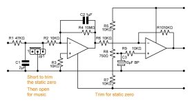
This is the servo I was thinking about, made according to servos' best practices (B.Aloia, B.Cordell, and others). The jumper is needed to short the servo's input to mass in order to trim the zero. Then connect the servo to the buffer output by removing the short. In a particularly lucky chance you will leave the jumper shorted to mass.
My last DBT has a 1mV offset moving slowly with the temperature. I couldn't appreciate big deviations because I didn't make the final pairs that hot. However, I used a servo the same.
In a buffer, you cannot use a feedback, loop in the audio band because the voltage gain is something less than 1.
So while we design a buffer, we have to think about a servo, which could be unnecessary if we are lucky, but we'll discover this when we power up the real thing. A good design must include the servo since it is conceived.
The Dartzeel NHB-108 has no servo but has trimmers to manually zero the offset when the alert light goes on. This is not acceptable IMHO.
This is the servo I was thinking about, made according to servos' best practices (B.Aloia, B.Cordell, and others). The jumper is needed to short the servo's input to mass in order to trim the zero. Then connect the servo to the buffer output by removing the short. In a particularly lucky chance you will leave the jumper shorted to mass.
Attachments
@Lee Knatta
My last post was intended to answer @anatech 's last post. You posted while I was writing.
I didn't know about others who tried the injection point I proposed. However, it IS in the signal path! At least in my schematic.
I'm not abandoning this idea, but I wanted to explore all the possible aspects. On the contrary, learning it was used by others, I am now convinced this will be a good solution.
Hi marigno,
I agree. A buffer has no voltage gain (which is the point). But, your servo sure does!
Just my personal viewpoint. Nothing wrong with a trimmer and as long as the drift is slow (which with temperature it is), and within acceptable limits, no problem. If you are chasing something that really doesn't matter in a practical sense, that may impair audio performance ... one has to wonder why?
Just keep it in mind in case you feel the servo is affecting sound quality. That's all.
Pete's (ostripper) servo is well thought out. Just keep transient behaviour in mind, which is power up and power down. Plus clipping events. Those may upset the applecart.
My own diamond buffer output stages tend to have low DC offset naturally, on their own. I do use them coupled to the voltage amp stage with DC feedback. In isolation they never had much in the way of DC offset. 30mV was the worst I measured, and it was stable.
I hope my DTB will show the same result as yours. I like the idea of avoiding a servo.
But I wouldn't say I like the feedback loop for the audio band.
I want to thank all members for bringing their contribution, I have now two important confirmations:
My goals are:
This "unhealthy" idea came to my mind when I gave help to a friend of mine in this project:
which is a DT(B) with 17db gain (neglect the op-amp VAS). This amp has no servo and no decoupled DC/AC feedback. It is 1U tall.
But I wouldn't say I like the feedback loop for the audio band.
I want to thank all members for bringing their contribution, I have now two important confirmations:
- a servo can be avoided (however a trimmer must be employed to zero the offset) because the DTB seems to be stable enough;
- the injection point (servo/trimmer) I want to use is not a thought of mine, others have used it successfully, which was my main concern.
My goals are:
- a power over 100W/8Ohm;
- a 2U cabinet for both channels (DTB only, no VAS).
This "unhealthy" idea came to my mind when I gave help to a friend of mine in this project:
This is the power supply.
I wasn't sure how to interpret this comment. A 100mV offset error at the output would deliver only 12.5 mA into a 8 ohm speaker, and modest added heat to the transistors sourcing that current. This is separate issue from quiescent bias current through the output transistors. Bias current should be measured with no load applied and should show little sensitivity to offset voltage.Even if 50mV is a negligible offset (I agree with this), we cannot neglect the problem.
My last DBT has a 1mV offset moving slowly with the temperature. I couldn't appreciate big deviations because I didn't make the final pairs that hot. However, I used a servo the same.
I agree completely with @anatec comments about avoiding servos. I enjoy servo design just for the challenge--- way more fun than Wordle or crosswords, IMHO. 🙂 But I will explore passive, trimmer-based approaches. We can always add DC servo if it seems attractive.
A related issue is the low frequency time constant/ -3dB corner. The corner frequency in the marigno design appears to be about 0.5Hz (post 27), which seems consistent with a Cordell servo described in his 2nd edition, page 223. I wonder why the corner is set so low. I've not done a survey of passive designs, but a Rotel pdf shows a series 100uF and 560R setting low the frequency gain corner, i.e. about 2.8Hz.
The low cutoff aggravates the challenges. You mention driving the amp from a mu-follower. I surmise the C101/C102 caps have to accommodate many tens of volts before bias settles. That's a lot of charge to be transferred through the bias network. Should you have a delay relay, commensurate with tube warm-up, to help speed bias?
Approaching from a specifications perspective, the amp impedance is about 50k. What minimum impedance would be acceptable? What -3dB cutoff frequency?
Thanks.
My last DTB has its VAS inside, it is DC coupled. The VAS has a feedback loop coming from the output of the VAS itself, and it is not AC/DC decoupled. The DTB stage has no feedback. So I was expecting a significant offset. Actually, the offset is 1mV, I don't remember how high was the offset after warming up the amp, however, it was very low. When I warmed up the amp I did it with the music, not touching the bias.
Nevertheless, I used a servo. But it delivers some subsonic artifacts. So avoiding the servo is a very good idea.
All values you see in the input part of the schematic are not validated yet. In this phase, I didn't care about their values. Maybe the 2 input capacitors will be housed in the VAS cabinet, and yes, there is a relay shorting the VAS output for 3 minutes after powering on. The minimum DC component on connecting cables is not a problem. The VAS has a very low output impedance, it comes from using a mosfet as the upper triode of the mu-follower.
I wish to set the highest possible cutoff frequency avoiding phase shift in the low part of the audio band. I'm not sure if the solution 100KΩ/diodes/100KΩ is the best one, this is another topic where suggestions are welcome.
Hi marigno,
I wish you good luck with your design, I hope it sounds good.
One observation, and I am not saying people shouldn't experiment. Pretty much anything you can think of has been tried. There are a few configurations that proved reliable with good performance, and we will always see a rehash of an unsuccessful design branch.
One thing I have observed is that avoiding negative feedback doesn't help you unless the design isn't good. In those cases negative feedback with increase bad behaviour. It isn't a magic bullet, and it is far from evil. So concentrating on avoiding negative feedback mat push you in the wrng direction.
- Home
- Amplifiers
- Solid State
- Diamond triple power power buffer