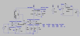
Is the "grid voltage" measured value, or calculated?B+ 158,94V
Plate 44,17mA
Grid -9,78V
Filaments 2,1V / 645mA
Measured resistor filament 15,16 ohms
15.16R*0.645A=9.7782V ... but where is 44.17mA cathode current???
The filament bias resistor current is sum of filament current and cathode current.
OK I will do, thanks.For testing it will be OK.
Set filament current to 0.65A, heats the tubes at least 1 hour and measure filament voltage again.
No.SSHV2 CCS current set to 100mA ..
CCS current is sum of load current and shunt stabilizer FET current (probably 10mA).
Set it to 55mA.
BTW why do you set B+ to 160V?
MeasureIs the "grid voltage" measured value, or calculated? Measured across the filament resistor
15.16R*0.645A=9.7782V ... but where is 44.17mA cathode current??? 44,17mA is anode/plate current
The filament bias resistor current is sum of filament current and cathode current.
I don't follow, I don't use any CCS only SSHV2 & OPT🤔No.
CCS current is sum of load current and shunt stabilizer FET current (probably 10mA).
Set it to 55mA.
SSHV2 is CCS feed shunt (FET) stabilizer.
Do you use separated stabilizers for each channel?
In #155 post the B+ values was different.
If independent SSHV2 serves each channels, at 45mA anode current the SSHV2 CCS must be set to 55mA.
The 45mA (15R filbias, 0.65A filament) is valid, if B+ is 190V.
Do you use separated stabilizers for each channel?
In #155 post the B+ values was different.
If independent SSHV2 serves each channels, at 45mA anode current the SSHV2 CCS must be set to 55mA.
The 45mA (15R filbias, 0.65A filament) is valid, if B+ is 190V.
It will cause a problem.
If the one channel 4P1L anode current is 45mA and the VAS tube is #26 with 5.5mA anode current, with other low currents the power consumption over 51mA.
Two channels consumes 102mA.
The SSHV2 CCS high voltage FET usually DN2540 or IXTP1N100.
The former very sensitive to spikes, I lost many of them. Not recommended here.
The last one can't do that current.
You must rebuilds SSHV2 CCS part with higher current capacity depletion MOSFET, for example IXTP08N100D2.
It’s done, the first CCS depletion mosfet is a IXTP08N100D2, happened the same to me....
Have I to set the SSHV2 CCS to 122mA?
Have I to set the SSHV2 CCS to 122mA?
Last edited:
I never use trimmer for CCS, only fixed value -good- resistor.Thanks Bela, how do you calculate the 6R to use in place of trimmer?
Some years ago I tested 08N100 based CCS with various resistor values.
Could you share the resistors values with CCS current?
I guess 1/4W power resistor is enough.
TIA
I guess 1/4W power resistor is enough.
TIA
I guess don't have to increase the CCS at SSHV2 for 4P1L that I set for 110mA (45mA each tube + 20mA SSHV2)?Bela the 26 has it's s own PSU and SSHV2
P=I*I*R
Below 100mW.
20mA spare current for shunt FET is more than enough.
Below 100mW.
20mA spare current for shunt FET is more than enough.
To reach the 45mA @ anodeNo.
CCS current is sum of load current and shunt stabilizer FET current (probably 10mA).
Set it to 55mA.
BTW why do you set B+ to 160V?
Set filament current to 0.65A, heats the tubes at least 1 hour and measure filament voltage again.
Done, measurements with 0.65A:
Left channel 2,43V
Right channel 2,17V
Done, measurements with 0.65A:
Left channel 2,43V
Right channel 2,17V
- Home
- Amplifiers
- Tubes / Valves
- DHT Headphone amp for HifiMan Edition XS
