All of the DHTs I've tried with the 6N6G seemed to work fine although I have no way of knowing if it's making full power or not. Whatever it is, it's enough.My amp is set up for 6V6 or 6P14P-EV. The 6V6’s amplification factor is too low to use just it and the 30 tube. I see two possible paths forward for the next amp with a 30 input tube. Either I try a three stage with a difficult to drive low AF final, or I try another two stage with an easier to drive higher AF final. The front end of the new amp will use battery filaments on the 30 for starters. I hope that sounds good. Could I use filament bias with batteries on the 30, or is that not workable?
I know Andy has also commented on the AF of various output tubes. I've always only considered it when I've looked at input tubes. Obviously I'm totally ignorant on the importance of AF when it comes to output tubes. So you're saying that the higher the AF of the output tube the easier it is to drive? I can't say I've even noticed specs for AF in most output tube data sheets. I guess I need to take a closer look.
The data sheet for the 6N6G does list it. It has an amplification factor of 58.
I also know zilch about filament bias. Andy has a lot of experience with it and I'm sure he can tell you which tubes will work with it.
I've used battery bias on the grid with all the DHTs I've tried. With the 30 I used exactly the same setup as I use with the 26 - a 0B2 VR tube to supply the plates and a Hammond 156C plate choke. Plate voltage to ground is ~90v or so. I use 3 AA batteries to supply -4.5v bias to the grids.
So you could use batteries for both filament and bias. As I understand it, filament bias requires a fairly serious resistor that dissipates a lot of heat.
All of the DHTs I've tried with the 6N6G seemed to work fine although I have no way of knowing if it's making full power or not. Whatever it is, it's enough.
I know Andy has also commented on the AF of various output tubes. I've always only considered it when I've looked at input tubes. Obviously I'm totally ignorant on the importance of AF when it comes to output tubes. So you're saying that the higher the AF of the output tube the easier it is to drive? I can't say I've even noticed specs for AF in most output tube data sheets. I guess I need to take a closer look.
The data sheet for the 6N6G does list it. It has an amplification factor of 58.
I also know zilch about filament bias. Andy has a lot of experience with it and I'm sure he can tell you which tubes will work with it.
I've used battery bias on the grid with all the DHTs I've tried. With the 30 I used exactly the same setup as I use with the 26 - a 0B2 VR tube to supply the plates and a Hammond 156C plate choke. Plate voltage to ground is ~90v or so. I use 3 AA batteries to supply -4.5v bias to the grids.
So you could use batteries for both filament and bias. As I understand it, filament bias requires a fairly serious resistor that dissipates a lot of heat.
Dissipating a lot of heat probably means that batteries are going to be drained quickly. Filament bias is going to require not using batteries for the filaments.
The amplification factor isn’t really about how difficult a tube is to drive, if I understand it correctly. That is more about Miller capacitance and the current required to overcome the Miller capacitance. AF is about the amps ultimate input sensitivity. With an AF of 58, pretty much any DHT small signal tube should be fine to fully drive the 6N6G, but I’m not sure about Miller capacitance for the 6N6G. Can you reach clipping with a normal 2 volt input signal? My guess would be yes with a 6N6G as the power tube. The 6P15P-EV has an AF of 18, and I can reach clipping with a normal 2 volt input. The 6V6 has an amplification factor of 9.8, and that is not sufficient to reach clipping in my amp. The 7868/7591 has an AF of 16.8 in triode, so it should be good for a two stage.
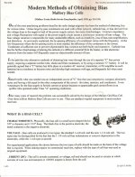
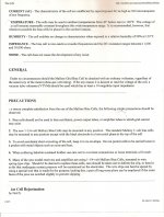
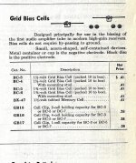
Battery bias is not a problem at all, it was used extensively in the latter 30s & early 40s in the voltage amplifier of many receivers. The bias cell used was very small since only microamps were required. As they aged sometimes they could be brought back to life simply by the application of a drop of water. Wiseoldtech has probably seen a few of these as he worked on these relics.
For Tizman's amp the easy way out is a common 9V battery at the bottom end of the 30 grid lead, the negative end pointed at the grid. Here again only microamps are required so long as the input signal does not draw grid current.
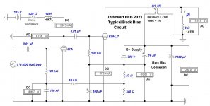
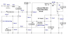
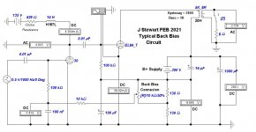
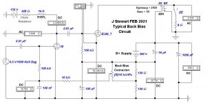
Another slick way out is back biasing, also popular with the olde timers. The required bias is developed in the amp negative return lead to the PS. Easy to do, no pain suffering or agony. I'd bet a few DM that Wiseoldtech has seen some of these too. 🙂
For Tizman's amp the easy way out is a common 9V battery at the bottom end of the 30 grid lead, the negative end pointed at the grid. Here again only microamps are required so long as the input signal does not draw grid current.
Another slick way out is back biasing, also popular with the olde timers. The required bias is developed in the amp negative return lead to the PS. Easy to do, no pain suffering or agony. I'd bet a few DM that Wiseoldtech has seen some of these too. 🙂
Attachments

The data you posted is the highly abridged version. Here's the data for the 6B5 which was the original version of the 6N6G. This is probably the most detailed data sheet I've ever seen, so you might enjoy it.
I've been unable to determine the name of the designer(s) but they did work in a research lab. 😉
The technical aspects are over my head, I just use the tube. It is quirky and I doubt many people here have listened to it. Have you?
---------------------------------------
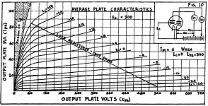
THX for the data sheet Charlie, it is the same as you posted in March. But I do appreciate you taking the time to be sure I've got enough information. So referring to the plate family of the 6B5 (p6) we see a loadline of ~7K.
Without counting the squares in order to estimate the plate resistance rp of the 6B5 slope of the plate curve looks about 1/3X the load Rl, so 21K. We can get a very good first estimate of damping factor (DF) of a tube by comparing the plate resistance to the load resistance in the circuit. DF is approx Rl / rp, so looks like about 1/3rd (7/21) for the 6B5. The OPT will reduce that further to the load. Very much like a pentode
------------------------------------------------------------------
As for the suitability of the 6N6G, all I can do is go by what my ears tell me. As I've said, I seem to be getting the same levels of realism and detail with my 26 - 6N6G SET that tizman has experienced with his 30 - 6P15P-EV combo.
I only have one other SET that uses DH tubes to compare it to, which is a 45 SET I built some time ago. It's the Bugle which was designed by Gordon Rankin and published as a DIY project in Sound Practices back in 1997.
----------------------------------------------------------------
Yes, I recall that amp, I was on Joe Roberts mail list for his entire series of magazines covering audio. Altho the 45 & 2A3 are excellent audio tubes they are somewhat difficult to drive. But its not an accident that many of the best sounding amps, both SE & PP, with or without NFB start with power triodes whose mu is ~5.
As an example, the DF of the 45 at 250V is 3900/1610 or 2.42. That will provide a lot more control to the loudspeaker than what is possible with a bare 6B5/6N6G...............DF ~1/3rd.
The users in the 30's noticed that when receivers were introduced with pentode output section. And so, the 'Triode Sound' was born. But the 6B5 sounded like a pentode, why would it not? the plate family is essentially a pentode.
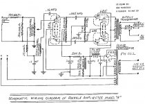
One amp using these is the Rockola, schematic attached here. Not sure how many were built. I think Wurlitzer used amps built by others, perhaps some were this one. The Wurlitzer amps I did see were usually PP 6L6s. Maybe someone could enlighten us.
----------------------------------------------------------------
Many designs published in the '90s faded quickly into obscurity. This one has not. It's a highly regarded design which is still recommended today as one of the best for those who want to build a 45 SET. I suspect hundreds (possibly thousands?) have been built since it was introduced. Perhaps there are better designs out there, but it's an excellent amp with a long-established track record. So if "catching on" is the measure of a good design, it seems to qualify.
Yet, somehow, my 26 - 6N6G "inverted" SET sounds better. And not just by a bit. More realistic and detailed. Much better soundstage. When playing thumpy, bass heavy tracks the bass is solid and well controlled. Not a hint of flabbiness. And it sounded better with all of the various types of DHT input tubes I tried, including the 30 and probably 8 or 10 others.
So, if the 6N6G is as much of a turd as has been suggested, the amp's superior sonics must be the result of my design brilliance.
-------------------------------------------------------------------------
Think I mentioned in March you can connect the 6B5/6N6G driver plate to the output plate & get a lower mu triode like the real thing. But audio power is limited, just as it is when we do the same thing to an ordinary power pentode. Someting you can easily try to satisfy your curiosity.🙂
Best to enjoy the amps you have. And do some experimenting as well. For me the music is just backgroud. The amp in my workshop uses a 6AU6/6AQ5 SE in a FB pair. Its been running trouble free since 1968.
Comma,🙄
Attachments
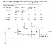
Adjustable Back Bias for the 30
This simple hookup allows the plate current of the 30 to be set over a range of 2.3 mA to 6.5 mA.😎 Max bias sets minimum current as we would expect.
This simple hookup allows the plate current of the 30 to be set over a range of 2.3 mA to 6.5 mA.😎 Max bias sets minimum current as we would expect.
Attachments
I don't have a scope so I can't objectively tell if it's clipping. Using a CD player for input I can turn the volume up fully without hearing anything that's disturbing to the ear. Not sure how much that means, there could be some clipping but it might not be extreme. I typically only listen with the volume control at 1/2 to 2/3 which is loud enough for me. Yes, I know the position of the knob is pretty much meaningless, but still.Dissipating a lot of heat probably means that batteries are going to be drained quickly. Filament bias is going to require not using batteries for the filaments.
The amplification factor isn’t really about how difficult a tube is to drive, if I understand it correctly. That is more about Miller capacitance and the current required to overcome the Miller capacitance. AF is about the amps ultimate input sensitivity. With an AF of 58, pretty much any DHT small signal tube should be fine to fully drive the 6N6G, but I’m not sure about Miller capacitance for the 6N6G. Can you reach clipping with a normal 2 volt input signal? My guess would be yes with a 6N6G as the power tube. The 6P15P-EV has an AF of 18, and I can reach clipping with a normal 2 volt input. The 6V6 has an amplification factor of 9.8, and that is not sufficient to reach clipping in my amp. The 7868/7591 has an AF of 16.8 in triode, so it should be good for a two stage.
As mentioned, with battery grid bias the battery life is essentially the battery's shelf life. If you use lithiums that's probably close to 10 years. Alkalines, I don't know, but years for sure.
If you use batteries to heat the tube, they will run down and need to be recharged regularly. I haven't tried it with this amp but when I was breadboarding a preamp I did. I forget which tube but the current draw was probably similar to the 30. I just used a normal AA battery for testing though, which doesn't have that much capacity. It lasted a while but as it drained the effect became increasingly audible.
Here's a battery that would work well with the 30 and last a while:
EnerSys Cyclon 2V 5AH AGM X Cell Battery - HAWK0800-0004 at Batteries Plus Bulbs
There are online calculators that will tell you how long you can go between charges.
I decided to use the little Meanwell SMPS instead and it works fine without any audible hum. I'm sure a battery would measure better, though.
Let us know your impressions of the 30 - 7591/7868 combo.
I don't have a scope so I can't objectively tell if it's clipping. Using a CD player for input I can turn the volume up fully without hearing anything that's disturbing to the ear. Not sure how much that means, there could be some clipping but it might not be extreme. I typically only listen with the volume control at 1/2 to 2/3 which is loud enough for me. Yes, I know the position of the knob is pretty much meaningless, but still.
As mentioned, with battery grid bias the battery life is essentially the battery's shelf life. If you use lithiums that's probably close to 10 years. Alkalines, I don't know, but years for sure.
If you use batteries to heat the tube, they will run down and need to be recharged regularly. I haven't tried it with this amp but when I was breadboarding a preamp I did. I forget which tube but the current draw was probably similar to the 30. I just used a normal AA battery for testing though, which doesn't have that much capacity. It lasted a while but as it drained the effect became increasingly audible.
Here's a battery that would work well with the 30 and last a while:
EnerSys Cyclon 2V 5AH AGM X Cell Battery - HAWK0800-0004 at Batteries Plus Bulbs
There are online calculators that will tell you how long you can go between charges.
I decided to use the little Meanwell SMPS instead and it works fine without any audible hum. I'm sure a battery would measure better, though.
Let us know your impressions of the 30 - 7591/7868 combo.
Thanks for the info and links. I know my amp is clipping because I can hear it. It’s not an accurate method, but it is obvious when it is clipping. If you can’t hear clipping at full volume on loud transients (especially single tone ones like piano notes) your amp is probably not clipping.
This simple hookup allows the plate current of the 30 to be set over a range of 2.3 mA to 6.5 mA.😎 Max bias sets minimum current as we would expect.
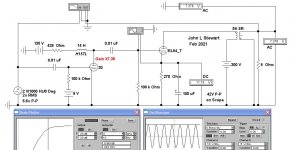
Thanks for the sims John.
I remember that you suggested connecting the input plates to the output plates, although you hadn't previously commented on how this would affect the tube's amplification factor.Think I mentioned in March you can connect the 6B5/6N6G driver plate to the output plate & get a lower mu triode like the real thing. But audio power is limited, just as it is when we do the same thing to an ordinary power pentode. Something you can easily try to satisfy your curiosity.
I tried it and the maximum power output does go down a bit but the sound is even more detailed and the bass is better. I need to spend more time listening but my initial impression is positive.
Does this method add feedback and affect the damping factor?
I'm wondering if that's the explanation for the sonic change or if it might just be the change in the voltage supplied to the input section plate. Previously, the input's plate was about 21v higher than the output section's plate due to the drop across the OT primary.
Would there be a difference between supplying the input plate directly from the output section plate and supplying exactly the same voltage from an additional RC in the power supply?
Last edited:
I remember that you suggested connecting the input plates to the output plates, although you hadn't previously commented on how this would affect the tube's amplification factor.
I tried it and the maximum power output does go down a bit but the sound is even more detailed and the bass is better. I need to spend more time listening but my initial impression is positive.
Does this method add feedback and affect the damping factor?
I'm wondering if that's the explanation for the sonic change or if it might just be the change in the voltage supplied to the input section plate. Previously, the input's plate was about 21v higher than the output section's plate due to the drop across the OT primary.
Would there be a difference between supplying the input plate directly from the output section plate and supplying exactly the same voltage from an additional RC in the power supply?
I’m confused. I thought this tube was a dual triode, with the first triode set up as a cathode follower for the second triode. How does that work with the plates tied together? I’ll have another look at the long datasheet.
OK Charlie, good to hear you like the sound after the change of hookup. Not surprising, the damping factor goes from something a bit less than 7/24 (Rl/rp) to about 2. That has much better control of the loudspeaker.
Development of the 6N6G concept appears to have started in early 1932, about the time I arrived! In the early sales piece we can see the small driver part separate from the following high mu power triode. So here was my take on the concept in 2003 complete with bench tests as pentode, triode & UL. More on all this later.🙂
-----------------------------------------
All Triode Distributed Load & Class A2 Positive Biased Triodes John L Stewart July 2017
The all triode distributed load (UL) circuit is something I looked at about 15 years ago. I had seen in the old tube manuals back more than 60 years ago some rather odd power tubes. These would include the 6AC5 & 25AC5, a pair of very high mu power triodes. Others are 6B5, 6N6G & 25B5, 25N6G.
All are now quite expensive, I guess the collectors need them to keep the old stuff running. I wondered about simulating them with easy to get tubes. If one thinks of it, most power pentodes when run as triodes with G1 & G2 strapped together have quite a high mu. I checked some 6F6s in that mode & found mu to be about 50, so OK for some kind of trial. If we check the old tube manuals we find that the recommended driver for the 6AC5 was the 76, a medium mu triode. The 76 is the same as the 6P5G but on the older base.
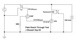
The trial circuit is quite simple, a 6F6 DC driven by the cathodes of parallel sections of a 6SN7GT. The anodes of the 6SN7GT could be alternatively connected to the B+ supply, the OPT CT or the plate connexion of the 6F6. That varies the amount of NFB applied to the anodes of the 6SN7GT. The resulting reach thru to the 6SN7GT cathode is (1/mu). I’ve put the test circuits & results into attachments.
I never did build the complete PP UL circuit. I realized that the driver plate(s) direct to B+ version was used commercially in some radios in the 30s. If you look at the base connexions on the octal 6N6G & 25N6G they are identical to many common power tubes such as the 6F6GT, 6K6GT, 6V6GT & so on. In the circuit they are self biasing, no cathode resistor required. But they did not catch on. Probably more expensive to build these tubes than the corresponding pentodes with there two cathodes, etc. An interesting exercise.
Here are links to a family of tubes suitable for an all triode PP UL amp.
http://frank.pocnet.net/sheets/049/6/6AC5GT.pdf
http://frank.pocnet.net/sheets/127/2/25AC5GT.pdf
http://frank.pocnet.net/sheets/127/6/6B5.pdf
http://frank.pocnet.net/sheets/084/6/6N6G.pdf
http://frank.pocnet.net/sheets/127/2/25B5.pdf
http://frank.pocnet.net/sheets/049/2/25N6G.pdf
Development of the 6N6G concept appears to have started in early 1932, about the time I arrived! In the early sales piece we can see the small driver part separate from the following high mu power triode. So here was my take on the concept in 2003 complete with bench tests as pentode, triode & UL. More on all this later.🙂
-----------------------------------------
All Triode Distributed Load & Class A2 Positive Biased Triodes John L Stewart July 2017
The all triode distributed load (UL) circuit is something I looked at about 15 years ago. I had seen in the old tube manuals back more than 60 years ago some rather odd power tubes. These would include the 6AC5 & 25AC5, a pair of very high mu power triodes. Others are 6B5, 6N6G & 25B5, 25N6G.
All are now quite expensive, I guess the collectors need them to keep the old stuff running. I wondered about simulating them with easy to get tubes. If one thinks of it, most power pentodes when run as triodes with G1 & G2 strapped together have quite a high mu. I checked some 6F6s in that mode & found mu to be about 50, so OK for some kind of trial. If we check the old tube manuals we find that the recommended driver for the 6AC5 was the 76, a medium mu triode. The 76 is the same as the 6P5G but on the older base.
The trial circuit is quite simple, a 6F6 DC driven by the cathodes of parallel sections of a 6SN7GT. The anodes of the 6SN7GT could be alternatively connected to the B+ supply, the OPT CT or the plate connexion of the 6F6. That varies the amount of NFB applied to the anodes of the 6SN7GT. The resulting reach thru to the 6SN7GT cathode is (1/mu). I’ve put the test circuits & results into attachments.
I never did build the complete PP UL circuit. I realized that the driver plate(s) direct to B+ version was used commercially in some radios in the 30s. If you look at the base connexions on the octal 6N6G & 25N6G they are identical to many common power tubes such as the 6F6GT, 6K6GT, 6V6GT & so on. In the circuit they are self biasing, no cathode resistor required. But they did not catch on. Probably more expensive to build these tubes than the corresponding pentodes with there two cathodes, etc. An interesting exercise.
Here are links to a family of tubes suitable for an all triode PP UL amp.
http://frank.pocnet.net/sheets/049/6/6AC5GT.pdf
http://frank.pocnet.net/sheets/127/2/25AC5GT.pdf
http://frank.pocnet.net/sheets/127/6/6B5.pdf
http://frank.pocnet.net/sheets/084/6/6N6G.pdf
http://frank.pocnet.net/sheets/127/2/25B5.pdf
http://frank.pocnet.net/sheets/049/2/25N6G.pdf
Attachments

The 6N6G is constructed just as you say.I’m confused. I thought this tube was a dual triode, with the first triode set up as a cathode follower for the second triode. How does that work with the plates tied together? I’ll have another look at the long datasheet.
With the plates tied it's operating the two sections in a sort of "quasi parallel" configuration. How that works electrically, I don't know. I don't grasp these technical aspects well.
To test the question I asked earlier - if the effect was simply voltage related - I did try adding another RC section to the PS and varying the resistor value. This brought the plate voltage on the input section closer to the output plate than it was when I had it connected to B+. It behaved the same as it had when it was connected to B+. Maximum output was higher than with the plates connected and it seems to sound essentially the same as connecting to B+. So the change in sonics is not simply due to a change in operating point.
OK Charlie, good to hear you like the sound after the change of hookup. Not surprising, the damping factor goes from something a bit less than 7/24 (Rl/rp) to about 2. That has much better control of the loudspeaker.
Development of the 6N6G concept appears to have started in early 1932, about the time I arrived! In the early sales piece we can see the small driver part separate from the following high mu power triode. So here was my take on the concept in 2003 complete with bench tests as pentode, triode & UL. More on all this later.🙂
-----------------------------------------
All Triode Distributed Load & Class A2 Positive Biased Triodes John L Stewart July 2017
The all triode distributed load (UL) circuit is something I looked at about 15 years ago. I had seen in the old tube manuals back more than 60 years ago some rather odd power tubes. These would include the 6AC5 & 25AC5, a pair of very high mu power triodes. Others are 6B5, 6N6G & 25B5, 25N6G.
All are now quite expensive, I guess the collectors need them to keep the old stuff running. I wondered about simulating them with easy to get tubes. If one thinks of it, most power pentodes when run as triodes with G1 & G2 strapped together have quite a high mu. I checked some 6F6s in that mode & found mu to be about 50, so OK for some kind of trial. If we check the old tube manuals we find that the recommended driver for the 6AC5 was the 76, a medium mu triode. The 76 is the same as the 6P5G but on the older base.
The trial circuit is quite simple, a 6F6 DC driven by the cathodes of parallel sections of a 6SN7GT. The anodes of the 6SN7GT could be alternatively connected to the B+ supply, the OPT CT or the plate connexion of the 6F6. That varies the amount of NFB applied to the anodes of the 6SN7GT. The resulting reach thru to the 6SN7GT cathode is (1/mu). I’ve put the test circuits & results into attachments.
I never did build the complete PP UL circuit. I realized that the driver plate(s) direct to B+ version was used commercially in some radios in the 30s. If you look at the base connexions on the octal 6N6G & 25N6G they are identical to many common power tubes such as the 6F6GT, 6K6GT, 6V6GT & so on. In the circuit they are self biasing, no cathode resistor required. But they did not catch on. Probably more expensive to build these tubes than the corresponding pentodes with there two cathodes, etc. An interesting exercise.
I'm not sure if the term "quasi parallel", which I used above, is appropriate. But with the plates connected does the input section of the 6N6G still operate as a cathode follower?
The increased damping factor is audible but I wouldn't say that it makes a drastic change. I could certainly live with it in either configuration, as the bass response was solid previously.
There is more detail, but I need to listen more to determine if this is "too much of a good thing" when it comes to the higher frequencies. The most obvious difference is in the output level. With the volume control all the way up I'm getting about the same level as when it was previously at around the 3/4 position. Which is not a problem since that's about the maximum I was using anyway.
Is it the result of increased NFB? I've seen designs with local, plate to plate FB but I don't recall seeing it used without a resistor or with a tube that's configured as a cathode follower. But my familiarity with the method is fleeting at best. Never tried it.
I assume that, since the output section is biased with an internal, unbypassed, resistor that some degenerative NFB is always present. Did you take that into account when you calculated the DF with the input plate connected to B+?
Thanks for posting your earlier experiments. I understand that the tubes you used are meant to simulate tubes like the 6N6G, presumably using tubes you had on hand. I can't say that I understand the results listed in the table, though.
I have read that the characteristics of the 6N6G can be obtained (or closely approximated) by using a combination of a 76 and a 6AC5. But when I compared the data sheets of the 76 and the 6SN7, which you used, they seem quite different. The paralleled plate resistance of the 6SN7 is quite a bit lower than the 76. The transconductance is about twice that of the 76 and the mu is about 50% higher than the 76. So I'm not sure how this would affect the results.
There also seem to be considerable differences between the 6AC5 and the 6F6, which you used. The plate resistance of the 6F6 is more than double that of the 6AC5 and the transconductance is roughly 2/3 that of the 6AC5. Again, I'm not knowledgeable enough to say how this might affect the ability make a valid comparison of this setup to what's going on with an actual 6N6G.
I also noticed a couple of things that puzzled me. First, you describe the method of connecting a pentode as a triode as connecting G1 and G2. I've always seen this done by connecting the plate to G2, most often using a low value resistor.
And the schematics you posted are SE circuits yet the OT model you used is, according to Hammond, a "universal" PP OT. So not sure if this would also have an effect on the results.
Last edited:
Three years later than the last bunch of posts, so I'll update. In this time I've committed entirely to high gain output tubes in triode mode in my SE amps. These have been:
EL38 - previously my choice, still good but I now prefer others
E80L in PSE - these surprised me - very clean and detailed, better than EL84 types, mu=20 in triode. Certainly a contender
EL12n - poor man's EL12 still cheap in Europe for new tubes. A very good sound
EL12 - just a little bit better than EL12n but now rare and prices have gone through the roof so not a contender any more.
So in view of the above I've made an amp with linked sockets for both EL12n and E80L. Both freely available in Europe.
Driver stage has alternated between 26, 46, 47 and 10Y. All better than 2P29L, 4P1L or 112A. 10Y now also rare and high prices, and I've finally settled on the 26. Plenty of stocks and It sounds very good indeed in filament bias with a resistor load. Resistor needs to be 39K or more so B+ around 350V. For hum purposes, put a grounded aluminium tube over the 26s. The synergy is very good between the warm and liquid sounding 26 and the neutral and clean EL12n or E80L.
So there we have it for a tried and tested combination which is simple, very good value and has the DHT sound in spades. Just 2 stages so very direct and detailed sound. I'm happy and all my 300bs, 2a3s and 6C4Cs are back in the cupboard. Putting the DHT first in the chain really works - it's a true DHT sound and I love it, especially on vocals and piano, but tone is good all round especially on acoustic instruments. I'm not going back to 300b/2a3 with high gain indirectly heated tubes. That was a cul-de-sac for me, never liked any of the driver tubes the way I love DHTs.

But an EL84 does not need a lot of gain. I was more interested in the 3a5 sound in the way that Andy ticks off boxes for his preferences.
You need to get 26 tubes from the USA. Buy a bunch while they are good value.Where do you get your type 26? Have you tried 3a5? Now they are really cheap and plentiful.
I've tried pretty much all the usual DHT small tubes - I invested in a lot of stock, most of which I've sold. I've listened again and again to all these in A-B tests over 15 years. My shortlist eventually came down to 26 or 10Y. Honourable mention to 46, 47, 2P29L, 4P1L, 112A. And 01A superb if you have the right circuit but I don't use active loads. Yes I tried 3a5 - good like a lot of other DHTs but didn't make the shortlist. I sold off a number of perfectly good DHTs - amongst others 30, 30 special, 31, 71A, 3a5, 2E22, 1624, 1G4, 1H4, 1J6G, 3B7.......
I tried 3A5 as preamp and much prefer #26 "sound".... but now -for years- use 801.
- Home
- Amplifiers
- Tubes / Valves
- DHT driver for triode wired SE EL84, 6V6 or EL34