Please enlighten us when you are able.
There are many articles in Zen series and various posts on C multipliers and high current regulation stages for power amps and yet the default here is always to end up with some massive bank of Cs in a CRC. The raison d'etre of this forum is elegant manipulation of electrons so it seems at odds to then use a series of massive reservoirs and small tubes to achieve a stable flow...
There are many articles in Zen series and various posts on C multipliers and high current regulation stages for power amps and yet the default here is always to end up with some massive bank of Cs in a CRC. The raison d'etre of this forum is elegant manipulation of electrons so it seems at odds to then use a series of massive reservoirs and small tubes to achieve a stable flow...
The simple cap multiplier circuits I tested outperform CLC by a decent margin.
The series regulated supply is virtually reference performance specs under all conditions.
I am always having a war inside the brain though, I tend to prefer simple circuits wherever possible.
Quite a few people avoid regulated supplies in class A because of the extra heat that needs to be dissipated, but a cap multiplier made from bipolars eliminates most of that issue, so that is the way I'm tending to think is the best solution.
The simple cap multiplier circuits I tested outperform CLC by a decent margin.
What is the meaning of "outperforms" exactly? Does it actually sound better?
What is the meaning of "outperforms" exactly? Does it actually sound better?
Noise and output impedance, I'm not at the stage of testing for sound/audio improvements.
All of my projects have virtually halted temporarily because of a lack of money or low on time.
Aside from parts count, cost and complexity, why aren't regulated supplies used in FW amp's input sections? Is it because of the way the output stage is biased and that the circuits are too simple? No benefit?
well , we can conclude that Papa is never making absolute overkill ...... each gadget having one stellar part/virtue , while other links in chain are made good enough for task
result - besides going dual mono which is always beneficial , some of amps you can improve somewhat , while some others you can't whatever you do
few examples are my Babelfish amps ...... and even Pumpkin - for which I only later found it's really iteration of X0 ....... and where primary difference is Shunty
and yes - regarding actual question - in some you can't use regs for input stages , due to biasing/modulating OS method
regarding regs and cap multis in power amps ...... I simply decided to ignore them , going overkill PSU route , thus having one choice less to make
Hi Vince,
The F5 is one such example where things can go bad if you regulate only the
front end.
Dennis
The F5 is one such example where things can go bad if you regulate only the
front end.
Dennis
I agree with Zen Mod here.
One simple tweak that might be worth trying, I've noticed Papa often uses localized RC decoupling for the front end circuitry, well why not try LC decoupling instead of RC.
It's always a rocky road trying to make improvements that don't compromise some other aspect of a design, but if you're determined to see it through to the end, it's the most enjoyable aspect of diy.
A lot of the time manufactures don't take designs to the nth degree because the cost/benefit ratio probably doesn't make too much sense for them, but if you have the genetic make-up resembling something close to a dead cat, it's all about the journey, the extra added-performance is just icing.
Ahhh thank you. The Sysiphus curse.
Me... I'm just tight.
That said, when you do get it working I'll certainly be interested in it 😉
Me... I'm just tight.
That said, when you do get it working I'll certainly be interested in it 😉
I'm looking at buying some 35V 220,000uF caps to put toward this project.
I only need 8 but MOQ is 20.
Anyone interested in purchasing some?
I only need 8 but MOQ is 20.
Anyone interested in purchasing some?
I'm looking at buying some 35V 220,000uF caps to put toward this project.
I only need 8 but MOQ is 20.
Anyone interested in purchasing some?
What are the dimensions of the caps?
63.5mm in diameter
117.5mm tall
Large Can Screw terminal
There is a 3 to 4 month lead time from time of order, they are a non-stocked item.
Hope that isn't a problem.
117.5mm tall
Large Can Screw terminal
There is a 3 to 4 month lead time from time of order, they are a non-stocked item.
Hope that isn't a problem.
Last edited:
PicoGenius Hahaha
Gee it's a great feeling when you discover something all on your own that Papa probably learned and already forgot about before i was born. Hahahaha
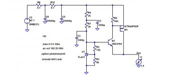
Earlier I said that to improve voltage dropout I would use bipolars, but just now I discovered if you make a compound pair with bipolar/mosfet combination you only lose 0.65Volts instead of the usual 4 to 5 volts of most mosfets.
Yeah Baby, time for my celebratory song https://www.youtube.com/watch?v=MTfbkpfFdB4
Hahaha
Gee it's a great feeling when you discover something all on your own that Papa probably learned and already forgot about before i was born. Hahahaha
Earlier I said that to improve voltage dropout I would use bipolars, but just now I discovered if you make a compound pair with bipolar/mosfet combination you only lose 0.65Volts instead of the usual 4 to 5 volts of most mosfets.
Yeah Baby, time for my celebratory song https://www.youtube.com/watch?v=MTfbkpfFdB4
Hahaha
Attachments
Last edited:

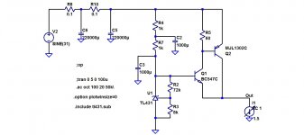
replace M1 with MJL1302A (PNP power transistor with ring emitter construction), replace Q1 with BC546C, and change R5 to 62 ohms. Presto, even better performance (wider bandwidth, lower output impedance) with zero MOSFETs.
And you may want to perform a few experiments to decide what is the optimum ratio of C2-to-C3. If the sum is constrained to be 2000 uF, is it optimum to divide the capacitance 1000+1000? Or is there some other ratio which works better? Using whatever definitions of "better" and "optimum" you prefer, of course.
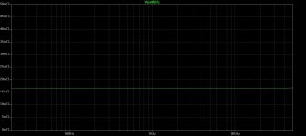
BTW, the professional EE way to display output impedance-vs-frequency, is with log log axes. Unless you're interested in less than one decade of impedance, i.e., not the ultrasonic behavior / 5th & 7th harmonic of 20 kHz.
And you may want to perform a few experiments to decide what is the optimum ratio of C2-to-C3. If the sum is constrained to be 2000 uF, is it optimum to divide the capacitance 1000+1000? Or is there some other ratio which works better? Using whatever definitions of "better" and "optimum" you prefer, of course.
BTW, the professional EE way to display output impedance-vs-frequency, is with log log axes. Unless you're interested in less than one decade of impedance, i.e., not the ultrasonic behavior / 5th & 7th harmonic of 20 kHz.
Last edited:
Already been there done that,
This is just a better way to use mosfets.
I'll change graph to log-log.
This is just a better way to use mosfets.
I'll change graph to log-log.
Last edited:
I actually get much better performance with this combination than bipolar/bipolar compound pair.
Muah hahaha
Muah hahaha
- Home
- Amplifiers
- Pass Labs
- Developing a Regulated Dual Rail Power Supply For FirstWatt Amps