I believe for transformers with dual secondaries dual rectifiers are preferable.
Definitely so.
if there is slightest chance of unequal current in opposite rails , it is better with two bridges , avoiding sorta dc saturation of donut iron
If you have separate secondary windings for the bipolar supply and use dual rectifier bridges does changing the relative phase of one secondary winding relative to the other have any effect on common mode noise reduction?
nope
bridges are there ....... being veeery directive devices
🙂
So you mean that no hi frequency noise can get past a bridge rectifier?
That doesn't seem right.
who said that ?
🙂
anyway - build and test , just two wires to change places of
can't hear it in praxis , but hey - elephant farted in my ears decade ago
🙂
anyway - build and test , just two wires to change places of
can't hear it in praxis , but hey - elephant farted in my ears decade ago
Ok.
I keep getting asked what is happening.
All my old circuits I had developed are on my old broken computer.
I kind of felt too lazy as well as bored drawing up the old UNPUBLISHED circuits again so decided on something completely different.
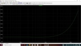
Posting performance specs first.
Around 100dB PSRR
Output impedance well below 10 mOhms
I have not had the chance to test this circuit except through simulation (I am on holidays).
Someone please test this.
I made it dumb simple. You could assemble it on protoboard.
I will post the circuit soon
I keep getting asked what is happening.
All my old circuits I had developed are on my old broken computer.
I kind of felt too lazy as well as bored drawing up the old UNPUBLISHED circuits again so decided on something completely different.
Posting performance specs first.
Around 100dB PSRR
Output impedance well below 10 mOhms
I have not had the chance to test this circuit except through simulation (I am on holidays).
Someone please test this.
I made it dumb simple. You could assemble it on protoboard.
I will post the circuit soon
Attachments

Last edited:
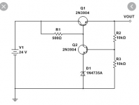
First off the bipolar devices used in the circuit were selected purely because they were in the LTspice Library, they are certainly not the best devices or the most appropriate devices.
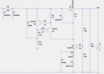
Some comments on the circuit
1) I have decided to use mosfets as the series follower output device, but you can use bipolars if you wanted to, but it will draw current away from the Zener reference so a Darlington arrangement might be best used here, having said that there is 10mA to 15mA running through the Zener circuit, so the bipolar could easily steal 8mA away and the Zener will still operate. I just chose to use a mosfet cause it requires less brain cells.
The circuit shows IRFP250 at M1 but I will be using IRFP150.
For the corresponding regulated negative rail I will be using IXYS IXTH52P10P as it is a reasonably good match to the properties of IRFP150.
IRFP150PBF Vishay Siliconix | Discrete Semiconductor Products | DigiKey
https://www.digikey.com/products/en?keywords=ixth52p10p
2) Q1 should be a TO220 device. It could be a mosfet or bipolar, but I think I prefer a bipolar in this location. I might change my mind though when I test further.
3) Q3 Could be a bipolar or mosfet. I am using a bipolar in simulation but may change to mosfet.
4) The voltage references used in the circuit U1, and U2 were not selected cause I thought they were good, use what ever are your favourites.
The regulated output voltage will be roughly twice the total sum of the 2 zener references. That is if two 5V references were used ie 10V total, then the regulated supply will be roughly 2 x 10 (plus 2 x Vbe) so a little over 20V.
5) If you need me to do the negative supply I will do that later.
Just keep nagging me. I will do it eventually.
Attachments

Last edited:
Ok.
I keep getting asked what is happening.
All my old circuits I had developed are on my old broken computer.
I kind of felt too lazy as well as bored drawing up the old UNPUBLISHED circuits again so decided on something completely different.
Posting performance specs first.
Around 100dB PSRR
Output impedance well below 10 mOhms
I have not had the chance to test this circuit except through simulation (I am on holidays).
Someone please test this.
I made it dumb simple. You could assemble it on protoboard.
I will post the circuit soon
The bloody 2 posts go across two pages so reposting previous post here.
The raw unregulated voltage should be 8V to 10V higher than the intended regulated supply value, eg If you wanted a 23V regulated supply then 31V to 33V would be needed.
Ok this is basically what I will build.
I hope someone else will also build and test this circuit, it has very good specs for a simple circuit.
I hope someone else will also build and test this circuit, it has very good specs for a simple circuit.
Attachments
Last edited:
Will there be PCB in the store ? 😛
More seriously, I do have some 2x22V donuts that I would like to use in a "classic" FW project, so I am tempted and looking forward to the negative version as well!
Is it really 2 x 100.000uF ? 😕
More seriously, I do have some 2x22V donuts that I would like to use in a "classic" FW project, so I am tempted and looking forward to the negative version as well!
Is it really 2 x 100.000uF ? 😕
1) If at least one person builds it and they like it then I will arrange for some pcbs to be made
2) 47,000uF, 47,000uF, R, 47,000uF, 47,000uF
You can use your existing CCRCC powersupply and it will still be fine.
It's not mandatory to use 47,000uF caps, just use what you already have.
2) 47,000uF, 47,000uF, R, 47,000uF, 47,000uF
You can use your existing CCRCC powersupply and it will still be fine.
It's not mandatory to use 47,000uF caps, just use what you already have.
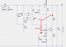
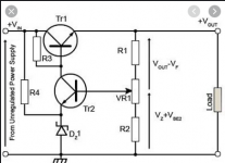
FYI, quite a few people feel it's a good idea to push a large constant bias current through the zener reference diodes. Now when the regulator must react to a varying load current at its output, the signal current through the zener diodes is a very small fraction of the total current. So the emitter voltage variation is much smaller, and the VREF to the regulator is much more stable. At least, that's what these folks believe.
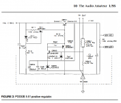
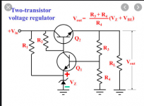
I've also attached a somewhat similar voltage regulator circuit by Walt Jung. Rbias in this schematic is labeled (R859) but not drawn, regrettably. 🙂
_
I've also attached a somewhat similar voltage regulator circuit by Walt Jung. Rbias in this schematic is labeled (R859) but not drawn, regrettably. 🙂
_
Attachments
Last edited:
I agree entirely. At least it has quite a significant effect in this circuit arrangement.
Increasing the current through the zener arrangement, improves output impedance of regulated supply but starts to reduce psrr.
I was biasing through R1.
12mA to 20mA seems to be the sweet spot, when biased this way.
I will also try biasing your way too. That may be a case of have my cake and eat it. We will see.
My only concern due to inexperience with Zeners is if I go with for example 20mA on a 5 V to 6 V Zener ie 100mW to 120mW dissipation, will I get decent reliability from 0.5 W zeners or will it be better to go with 1 W zeners.
Last edited:
Wow.
I am amazed at how close that circuit is to what I have cobbled together.
Trial and error and 1/2 a brain cell goes a long way.
I’ve never read a single electronics book. Hahahaha
I am amazed at how close that circuit is to what I have cobbled together.
Trial and error and 1/2 a brain cell goes a long way.
I’ve never read a single electronics book. Hahahaha
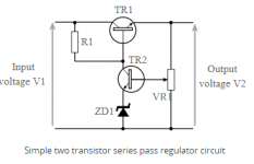
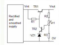
It's a fairly common example circuit, seen in MANY books and websites, precisely because it's so simple. At heart there's two transistors and a zener diode. Simple.
You can change a resistor into a current source, you can add extra zener bias current, you can add a bootstrapped PNP emitter follower for gigantic gain boost (thus gigantic ripple reduction at 120 Hz), you can add ballasting resistors to avoid instability with capacitive loads. But at heart it's still a two transistor circuit. One transistor drives the load, the other transistor acts as the error amplifier.
_
Attachments
Last edited:
- Home
- Amplifiers
- Pass Labs
- Developing a Regulated Dual Rail Power Supply For FirstWatt Amps