Does anyone have good operating points for the 10Y tube as a driver?
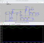
I'm about to breadboard a direct-coupled 2A3, driven by a choke-loaded 10Y (Lundahl 1668, 100H/25mA) with a stacked power supply (attached screenshot). Altec 15095A input transformers will give the signal the necessary gain. This is expanding on the experiment with the 26-2A3 circuit shown above.
I've only been able to find one datasheet for 10Y, which is all about Class C telegraphy, not Class A audio amplification. On Vinyl Savor, Ale' Bartola's website, and in one or two fora, I've read that 10Y is a "special" version of the type 10, and that it's similar to 801A, which is a much higher voltage and current-capable tube than the 10. The "Typical Operation" section of the datasheet for 801A kind of reads like a continuation from the highest operating point of the 10.
Given all of that, I'm going to try running 10Y at the highest manufacturer-recommended op point of the 10 -- 350Vak/16mA -- assuming that it is likely to be linear and perform well.
The 2A3 will be at 250Vak/60mA, and grid biased.
Attachments
Thanks, Bigun! That's a policy change since the last time I paid attention! 😆
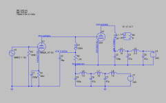
Here is the schematic of the 45 SET that's on the breadboard, which I've been listening to for the last couple months while waiting for the Lundahl anode chokes to arrive. I ended up adjusting the voltages so that the 26 is operating around 133V/5mA and the 45 is at about 250V/34mA. Experience has shown me that the Goldilocks Zone for the 26 is 4.7mA to 5mA, and no more than that. After many trials of various operating points on both tubes, this combo is just right.
This sounds excellent. I plan to build it as a standalone integrated amp once all the experimenting is done.
The schematic is descriptive, as I used parts on hand so as not to purchase any more for now. For a final build, I would probably boost the two 39uF caps (Axon polypropylene film) to 100uF film, but that's about it. This is an amp I could happily live with in my small home office with the single fullrange driver setup in here.
A note about the OPTs: these are custom units that a friend ordered from Tektron in Italy and sold to me a few years ago because they no longer suited the project he was working on. They were spec'd for 3.5Kz primary impedance with secondaries at 6ohm and 10ohm, rated for 10 watts, and have M6 laminations. I have the 15ohm Lowthers connected to the 10ohm secondaries, which produces a 5.25K load impedance on the 45 tubes for an estimated damping factor of about 3.28. The 6ohm secondaries connect to headphones via an L-pad with two 3-ohm non-inductive wirewound resistors per channel, which sounds surprisingly good as well. Overall this design is a very good use scenario for these Tektron OPTs that were customized for someone else's project, and that feels good!

Oops! Thank you, Pyka, for pointing that out.
Major omission in the schematic. The cathode of the 45 does indeed connect to the negative leg of the upper power supply. Don't know how I neglected to include that in the drawing, but it's there, just as in the previous versions of the circuit that I posted above.
Major omission in the schematic. The cathode of the 45 does indeed connect to the negative leg of the upper power supply. Don't know how I neglected to include that in the drawing, but it's there, just as in the previous versions of the circuit that I posted above.
If you use 10Y at about 340-350V a-c voltage and near to -30V bias, the anode current is relatively small, and the operating point near the curved sections.

Try larger current, over 20mA.
The 10Y is more robust tube that earlier 10, so it's dissipation limit is higher.

http://vinylsavor.blogspot.com/2012/02/tube-of-month-10y.html
You want to use this tube at 14.581 kOhm load (12566R from 100H/20Hz + 2.015k resistor).
This tube max. anode dissipation is 10W, so at 350Vak the maximum anode current is 28.5mA. At recommended 80% dissipation the current is about 23mA.
The 2A3 is easy drive tube, so at 250Vak 90Vpp grid swing is enough.
If you use 10Y at 350V, 23mA (about -22V grid voltage), the +/-45V swing will be in linear range of curves.
Try larger current, over 20mA.
The 10Y is more robust tube that earlier 10, so it's dissipation limit is higher.
http://vinylsavor.blogspot.com/2012/02/tube-of-month-10y.html
You want to use this tube at 14.581 kOhm load (12566R from 100H/20Hz + 2.015k resistor).
This tube max. anode dissipation is 10W, so at 350Vak the maximum anode current is 28.5mA. At recommended 80% dissipation the current is about 23mA.
The 2A3 is easy drive tube, so at 250Vak 90Vpp grid swing is enough.
If you use 10Y at 350V, 23mA (about -22V grid voltage), the +/-45V swing will be in linear range of curves.
Just recording here that I still have the 26 tubes in place as drivers, and tried removing the cathode bypass capacitors to reduce gain and hear how it might affect the sound character. It resulted in a harsh, rhythmic noise that sounded like an angry insect buzz. I wasn't expecting that.
I thought it might be a grounding problem, so I checked all the connections, which were fine. Operating voltages throughout the circuit were also normal. I then put the cathode bypass caps back in and the noise went away.
I'm sure some here will understand the physics of it, but something about the directly-heated triode, DC filament supply, and/or the direct-coupled topology requires a cathode bypass cap.
euro21: Thank you for that advice. I've been doing more research on the 10Y and plan to breadboard it this weekend. Will report back when there are results.
I've read this thread from start to finish and learned a lot. Thank you to all the contributors for a lot of great content and ideas. I had been thinking of another 300B amp, but this thread had inspired me to move forward with a 2a3 amp instead. I have a pair of Monolith SX-11 5k output transformers that I bought from another member that I plan to use. My speakers are closer to 6 ohms, particularity below about 1500Hz, so reflected load will be closer to 4k.
I plan to use this to drive an open baffle line array with ~98db sensitivity. These play down to about 150Hz, where a separate powered woofer tower takes over, so I've incorporated a simple switchable high pass filter before the 2a3.
I plan to build this as a pair of monoblocks. I run long interconnects (7M) between my line stage and amps, so I've also incorporated an input transformer to allow balanced connections.
I wanted to use a DHT driver so I decided to use the EML 20A and will probably also go with the EML 2a3 mesh plate for the output tube.
Some comment.
1.) IMO C17 is unnecessary, if you haven't really silent HV PSU (like parafeed amplifier). It may cause more trouble than it does good.
2.) M-Resist Ultra is copper-magnanin foil resistor. Even if good in crossovers (where dissipation is moderate), it's NOT 30W resistor! Peek 30W, continuos 3W.
Try to choose "real" power resistor!
The filament bias resistor/s/ dissipates 14.7W (2x7.35W), so at least 30W continuos dissipate capable 15R//15R resistors required.
I usually use wound wire resistors, if available, non-inductive versions (for example Dale NH family).
Appropriate -large- heatsink also required. For example I use for 10W dissipation old /computer/ server processor heatsink.
3.) EML20AM at 352V, -13V (voltage on filament resistor+half of filament voltage) almost in cutoff state in the curved part of Ua-Ia.
Must to try another operating point (even at larger current).

As can you see, the most linear part of curves (at inductive load) is between 20..30mA (at about 350V).
For example at about 25mA current (about 350V) requiring -7.5V bias.
7.5V-(5V/2)= 5V
5V/1.4A= 3.57R
If you use 4R filament bias resistor, the estimated bias -8.1V.
At about 350V, -8.1V the current about 22..25mA.
The limiting factor is the load (choke) saturating current. For example LL1668 (100H) 25mA version is good.
If you haven't appropriate anode choke, try to use gyrator or cascode CCS as anode load.
p.s.
If you want to use SUT, why not use fixed bias via secondary?
1.) IMO C17 is unnecessary, if you haven't really silent HV PSU (like parafeed amplifier). It may cause more trouble than it does good.
2.) M-Resist Ultra is copper-magnanin foil resistor. Even if good in crossovers (where dissipation is moderate), it's NOT 30W resistor! Peek 30W, continuos 3W.
Try to choose "real" power resistor!
The filament bias resistor/s/ dissipates 14.7W (2x7.35W), so at least 30W continuos dissipate capable 15R//15R resistors required.
I usually use wound wire resistors, if available, non-inductive versions (for example Dale NH family).
Appropriate -large- heatsink also required. For example I use for 10W dissipation old /computer/ server processor heatsink.
3.) EML20AM at 352V, -13V (voltage on filament resistor+half of filament voltage) almost in cutoff state in the curved part of Ua-Ia.
Must to try another operating point (even at larger current).
As can you see, the most linear part of curves (at inductive load) is between 20..30mA (at about 350V).
For example at about 25mA current (about 350V) requiring -7.5V bias.
7.5V-(5V/2)= 5V
5V/1.4A= 3.57R
If you use 4R filament bias resistor, the estimated bias -8.1V.
At about 350V, -8.1V the current about 22..25mA.
The limiting factor is the load (choke) saturating current. For example LL1668 (100H) 25mA version is good.
If you haven't appropriate anode choke, try to use gyrator or cascode CCS as anode load.
p.s.
If you want to use SUT, why not use fixed bias via secondary?
Last edited:
@euro21 - thanks for the feedback. I had totally forgotten about adding half the filament voltage when calculating the bias. 😳 I haven't purchased the plate chokes yet, and getting the LL1668 at the standard 25mA will be less expensive than a custom gapping, so I like your suggestion of upping the bias.
I'll probably stick with filament bias, particularly since lowering the bias voltage makes it that much easier. I'm going to do some experimenting with the Mundorf resistors. Three 12ohm in parallel will reduce power dissipation to less than 3W each, and I have some pretty beefy heatsinks I'm planning to use that I'll mount the filament resistors and regulator to (should have last than 20C rise with this power dissipation).
I'll probably stick with filament bias, particularly since lowering the bias voltage makes it that much easier. I'm going to do some experimenting with the Mundorf resistors. Three 12ohm in parallel will reduce power dissipation to less than 3W each, and I have some pretty beefy heatsinks I'm planning to use that I'll mount the filament resistors and regulator to (should have last than 20C rise with this power dissipation).
Just to add a bit of variety to the main issues, I used to use the 2a3 myself but was never satisfied with the driver tube, so moved on. However I just built a ECC40 stage which sounds much better than I expected - not sure why I didn't try this previously. I have it connected to a PSE 4P1L output stage but it has enough gain to drive a 2a3. It was a popular European tube at one time but was phased out since it has a rimlock base. But that's no problem and there are still ECC40s around to buy - it's not a rare tube. For those interested this is what I built. I also preferred the sound to a similar E80CC stage - the piano sound is very natural, as are acoustic instruments in general.

It's a good idea. Did you find some Philips-group ECC 40s?
You can improve the stage using grid bias or filament bias (works very well for indirectly heated triodes too).
It transpires that even DC Link capacitors are noticeable in the cathode position; I helped a friend's 45 stage this week - it recovered its natural sound when the DC link bypass was designed out.
Yes - I have Philips ECC40. They made most of them. Tungsram made some - I don't know how different they are. They look quite similar. It's a very good sounding tube - very natural on acoustic instruments. Piano tonality is the clincher for me, it absolutely has to be right.
The downside with DC Link caps is that they are big. In a restricted space I've got almost as good results with AudioNote Kaisei electrolytics in parallel with Elna Silmic II. I did a big shootout and they did very well.
What ways do you use to design out bypass caps?
The downside with DC Link caps is that they are big. In a restricted space I've got almost as good results with AudioNote Kaisei electrolytics in parallel with Elna Silmic II. I did a big shootout and they did very well.
What ways do you use to design out bypass caps?
My acoustic musician friend helped sharpen my judgement of whether my amps were achieving natural sound, decades ago. Tweaking the amps for Piano sound took the longest time to gain her approval!
Designing out capacitors from positions where they carry the whole music-signal current is usually worth the effort.
With the low 4V of bias you have there, the easiest way is just to aim a current source at a low value resistor. Or run a current through the heater and into the cathode resistor, if you have one of my regulators to hand.
There is still a cathode resistor, but low enough value that a bypass is not needed.
When the bias voltage is high (DHT power valves), the power burn gets too much.
Switching to grid bias means no resistor or capacitor in the cathode; and this is better still. I use my bias regulator for lowest noise and stable impedance.
I don't have the technical knowledge that Rod does, but will confirm anecdotally that implementing direct-coupled stages (no capacitor between driver & output tubes) and grid-biasing the output tube are together the greatest single improvement I've ever made. Higher drive current is also crucial.
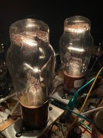
Just reporting that I've begun setting up the 10Y tubes on the breadboard, starting with the DC filament voltage. Using parts on hand, it took a lot of trial and error. What ended up working was a single 6.3V transformer that feeds two diode bridges and passive filter networks -- one for each 10Y tube, as shown in the attached drawing.
Each filament is running at 7.5VDC. The topology is not ideal. Of course, I'd prefer to have a separate transformer for each channel, and would do that in a final build. But this should be OK for listening tests, right?
Each filament is running at 7.5VDC. The topology is not ideal. Of course, I'd prefer to have a separate transformer for each channel, and would do that in a final build. But this should be OK for listening tests, right?
Attachments

I finally have the 10Y up and running at a decent operating point (about 250Vak/12mA) and the entire circuit dialed in for a first listening test. Again, this 10Y direct-coupled to 2A3 (at 250Vak/60mA) with a stacked power supply, similar to what is shown in the attached screenshot.
It makes sound; however, there is a loud 120Hz hum that I believe is coming from the DC filament, similar to what I experienced at this post, when I had a 43mV ripple across the 1.5VDC filament of the 26 tube as driver. I remedied that by adding more of the same 125uH mini chokes in series to create a CLCLC filter, which resulted in 8mV AC ripple across the filament, and which was quiet enough for many enjoyable listening tests.
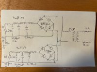
I'm now using four 4mH mini chokes in series with the same capacitors to create one LCLCLCL filter in each channel (image above but also attached here for convenience). My guess is that the 5-fold increase from 1.5V of the 26 tube to 7.5 V of the 10Y has made the AC ripple more audible again. If I want to keep the passive DC filter, which sounds good (it worked well with the 26), then I'll need to swap in higher inductance chokes and/or add more of these with additional high value capacitors.
It's hard to find inexpensive mini chokes with enough inductance and current. There are plenty of mini common mode chokes with the right inductance and current capacity, but I don't think they'd work in this application.
These 4mH 16A mini chokes are a pretty good deal at less than $4.50 ea. but do not quite do enough for this application, unless I simply add more LC stages: https://www.mouser.com/ProductDetail/Schurter/DENO-25-0001?qs=A5k8bsa1loDfpdVSyZOXZg==
I was trying to get a decent DC filament supply for the driver stage without spending a lot of money, but now it might be time to try batteries, a chip, or the Rod Coleman regulator.
It makes sound; however, there is a loud 120Hz hum that I believe is coming from the DC filament, similar to what I experienced at this post, when I had a 43mV ripple across the 1.5VDC filament of the 26 tube as driver. I remedied that by adding more of the same 125uH mini chokes in series to create a CLCLC filter, which resulted in 8mV AC ripple across the filament, and which was quiet enough for many enjoyable listening tests.
I'm now using four 4mH mini chokes in series with the same capacitors to create one LCLCLCL filter in each channel (image above but also attached here for convenience). My guess is that the 5-fold increase from 1.5V of the 26 tube to 7.5 V of the 10Y has made the AC ripple more audible again. If I want to keep the passive DC filter, which sounds good (it worked well with the 26), then I'll need to swap in higher inductance chokes and/or add more of these with additional high value capacitors.
It's hard to find inexpensive mini chokes with enough inductance and current. There are plenty of mini common mode chokes with the right inductance and current capacity, but I don't think they'd work in this application.
These 4mH 16A mini chokes are a pretty good deal at less than $4.50 ea. but do not quite do enough for this application, unless I simply add more LC stages: https://www.mouser.com/ProductDetail/Schurter/DENO-25-0001?qs=A5k8bsa1loDfpdVSyZOXZg==
I was trying to get a decent DC filament supply for the driver stage without spending a lot of money, but now it might be time to try batteries, a chip, or the Rod Coleman regulator.
Attachments
Last edited:
Do yourself a favor and get PSUD so you can ballpark a good setup for yourself. Lots of guides here and elsewhere on the Internet for how to use it. You will be able to figure out what parts you need to hit your target without as much trial, error, time, and expense.
As you said, you have much less headroom to filter your filament DC with the 10Ys since they require a higher voltage. It may be best to get transformers with a higher voltage for them.
You will want to wait until you've settled on a specific circuit before you order one of Rod's regulators. You can use a single pair for multiple tube types but the possibilities are dictated by the current and voltage ranges you're dealing with, along with your ability to dissipate the heat.
Try to use virtual cathode for 10Y: two 33R (or 100R pot) from filament pins, the common point tied to cathode R//C.there is a loud 120Hz hum that I believe is coming from the DC filament, r.
p.s.
Why do you use C2?
Last edited:
Thanks, Thekak and euro21. I do have PSUD. I've always used it to design high voltage power supply filters but will try it with low voltage filaments.
At your suggestion, I placed a 100R hum pot across each 10Y filament and attached the wiper to the cathode resistor and bypass cap. It lowered the hum, but not enough for listening to music. I'll be receiving a large bin of parts tomorrow, so perhaps there are things I can use to eliminate this hum.
At your suggestion, I placed a 100R hum pot across each 10Y filament and attached the wiper to the cathode resistor and bypass cap. It lowered the hum, but not enough for listening to music. I'll be receiving a large bin of parts tomorrow, so perhaps there are things I can use to eliminate this hum.
Are you sure, that hum source is 10Y filament supply?
As you can see, the most critical part is B+ (lower stack of PSU chain).

p.s.
Sometimes old DH tubes are very sensitive to radiated hum (due to the PTs, chokes, high current wires etc.).
Try to wrap 10Y -temporarily- with aluminium folie and connect it to ground.
I used it with #26 many times and sometimes help a lot.
As you can see, the most critical part is B+ (lower stack of PSU chain).
p.s.
Sometimes old DH tubes are very sensitive to radiated hum (due to the PTs, chokes, high current wires etc.).
Try to wrap 10Y -temporarily- with aluminium folie and connect it to ground.
I used it with #26 many times and sometimes help a lot.
Thanks for the foil suggestion. I'll try that. It might help because the breadboard is crowded and not all the transformers and inductors are rotated 90* with respect to one another.
I think the 10Y filament is part of the hum source because the hum pot did lessen the noise. It's probably not the only source, though.
To answer an earlier question, one of the reasons for C2 is to shunt AC ripple and noise to ground. C2 and R2 form an additional RC stage on the lower power supply rail.
When the 26 was the driver, I fixed the hum by adding filtering to the filament supply. The only thing that has changed with 10Y is the higher operating and filament voltage, which probably amplifies existing noise sources from when 26 was there. I'll keep working on that lower power supply rail and its junction with the upper one.
- Home
- Amplifiers
- Tubes / Valves
- Developing a 2A3 SET