First try
I'm happy to report 5 hours of preliminary testing and listening to dx-amp...
One channel performing great the other gets a bit hotter and looks like it's clipping (on the scope). However on the speakers I was testing it sonds fair.
I'll have furter tests on this channel using signal generator and post some pictures.
I thank everyone for the support.
Charlie
P.S. All components and values used are standard for the latest version of dx-amp except for R10 (4.7k).
One good and other hot...the same as happened with other Rumanian
hehe...this is very strange.... i am not very lucky related Rumania...a pitty that...beautifull country...but 2 folks having problems...and almost the same..one channel good and other channel bad.
Give a good check...of course something is "different" at the one that is hot.
Good luck.
I hope you appreciate the sonics.
............. some comments about cheap simple Dx amp............
The amplifier, for sure clips.... has any anti clipping feature..for sure..as this is not good for sonics.
And will clip very hard above 20 volts RMS into your meters... even perfect and well aligned it will make that awfull clipping noises (square waves sound terrible)
Good luck...your images and reports will be fully appreciated.
I am now a days working with another model...some evolution to high power.... and it clips awfull when reach 360 watts RMS..... but i cannot observe that hard clipping for too long as my speaker smells burned....for sure.....
During clipping you will have almost a DC signal from the supply.... the supply strengh will be transfered, as transistors will be saturated.... enormous energy goes there.... 4 to 6 times the average power goes to speaker....also sounds awfull.
It is a good idea to include a 100 picofarads condenser, from Q2 (the feedback transistor from the differential pair) to ground.
Having speaker wire, the traditional, very standard, and terrible parallel cable used to "abatjours"....home ligthing to readings.... those cables use to portable appliances inside our home.... that one...beeing used, with a length bigger than 1.5 meters...may create problems.... this way, a coil can be used to avoid problems.
If your cable is short....do not worry and be happy..... check if zobel network is soldered to ground....and install the boucherot if needed...that coil.... 15 to 30 turns over a 10 ohms, 1 watt resistance...wire can be 1 milimeter diameter or half milimeter..of course ...needing, you can use other resistance values.... the effect can be smaller of greater, depending the value you install.... make that one around 10 ohms not to drift too much from the standard traditional values used by "all world amplifiers"...or..."removed, now a days, from all world amplifiers"
Heat can be unbalance of currents...off set trimpot may fix....can be higher bias than the normal (40 to 100 miliamps)... heatsink can he smaller than the needed...also drivers need to have heatsinks...attach aluminium to them..they cannot work too much hot..use "L" shape aluminium or bend it to the shape.... 15 milimeters to 20 milimeters each side (if squared) will be enougth.
Heat can be result of oscilations.... in this case you will be able to feel some heat over the zobel output filter...that 10 ohms with 100N condenser to the ground..from the output line to ground...if this one is hot..for sure you have oscilations....also oscilations can be perceived measuring AC voltage into the output.
Input detected Radio frequency and be "eated", finished, fixed, repaired, removed, using 102 capacitor in the place of the small unit provided (to people that do not leave near Radio Frequency transmitters).... the small unit was selected as the big majority of people do not have radio frequency, in big intensity, around their homes, the exception can he Radio Amateus...very rare those folks (Me).
Feedback condenser, 102 to 103 can be soldered into the Q2..from base to emitter ....yeah...base to emitter.
Oscilations that can start into differential can be "killed" using capacitor, 100pf...inter connecting the differential bases....the condenser will connect both bases.
Increasing in the Miller condenser may fix some oscilation problems.
Condenser from drivers and output transistors, connected to ground will fit oscilations too.... give a try....if needed...as this is one of the most probable causes of heat..... the first one is the bias adjustment..second one the heatsink dimension..third one is the thermal drift because or hot drivers.... fourth may be VBE multiplier not so well installed...and fifth will be the oscilations.
Oscilations can he trigered by input audio...and also can be a result of the amplification of signal that came from the CD player (it has oscilators and some noises goes together the audio line out)... also can start in the amplifier itself.
Remember that feedback condenser is 22 to 27 picofarads...also the miller one.
regards,
Carlos
Charly_fd....having images, if good ones with big resolution.
Do not only publish in our forum...also...send directly to me.
panzertoo@yahoo.com
Full resolution.... 4 Megabytes images will be gladly received...till the 50 gigabytes limit (hehe)
They will serve for History of the Dx amplifier.
regards,
Carlos
Do not only publish in our forum...also...send directly to me.
panzertoo@yahoo.com
Full resolution.... 4 Megabytes images will be gladly received...till the 50 gigabytes limit (hehe)
They will serve for History of the Dx amplifier.
regards,
Carlos
Thank you Carlos!
It is normal to have the same (almost) problems: Today I was playing with usernamex's amplifiers")
I found the short on one channel that was causing the problems with realy high temperatures. After that, I reseted the bias and offset and it reads ok on all control spots. It gets warmer than the other channel but not something to worry about for the moment.
I suggested larger heatsinks to start with.
The clipping I was seeing on the scope was not caused by the amp: the source was rubish. Using sine signal (60Hz, 440Hz and 4kHz) the output was pure all the way up to aprox 5W (630mV input with R10 at 4.7k and 10ohm load). We will test full power later on.
Will keep you posted. The pictures are in my phone for the moment I'll send them tomorrow.
It is normal to have the same (almost) problems: Today I was playing with usernamex's amplifiers
I found the short on one channel that was causing the problems with realy high temperatures. After that, I reseted the bias and offset and it reads ok on all control spots. It gets warmer than the other channel but not something to worry about for the moment.
I suggested larger heatsinks to start with.
The clipping I was seeing on the scope was not caused by the amp: the source was rubish. Using sine signal (60Hz, 440Hz and 4kHz) the output was pure all the way up to aprox 5W (630mV input with R10 at 4.7k and 10ohm load). We will test full power later on.
Will keep you posted. The pictures are in my phone for the moment I'll send them tomorrow.
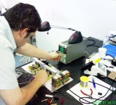
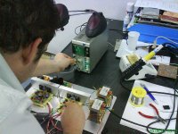
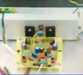
Now i have some images that arrived from Charlie_fd
The equipment is beeing debugged by Charlie that already found a small problem...now things will run better.
Thank you to help Dx amplifier Charlie.
This equipment is the usernamex units.
Image was made using cell phones, Sony Ericsson W850i.... and arrived here with 380K bytes...i had to reduce to fit the forum 100K limit.
Good images as made by a cell phone...original ones were very nice.
You see our friend Charlie....a very young man helping Dx amplifier and Dx team to smile once more.
regards,
Carlos
Attachments
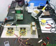
Another image, made my Charlie_fd from Rumania
I think they are friends...Charlie and Usernamex.
A very good help you are giving him Charlie.... i perceived him, Usernamex, hardly frustrated because the unit did not worked first moment.
I hope, every Dx constructor can have a friend alike you around.... my hairs will not turn completely white..for sure.
regards,
Carlos
Attachments
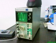
Lovely scope yours..... really small and pretty.
I could read nothing in the scope panel... the last image posted.... that one is made in your country, i suppose...very nice unit.
Seems that we need to have very thin fingers to hold it... tiny and pretty one...very nice.
regards,
Carlos
I could read nothing in the scope panel... the last image posted.... that one is made in your country, i suppose...very nice unit.
Seems that we need to have very thin fingers to hold it... tiny and pretty one...very nice.
regards,
Carlos
Attachments
Somewhat off-topic
The scope is a C1-94, made in ex-SSSR, Russia or Ukraine, I'm not sure, in the 1980's. I used to have one too and it was actually a very nifty little single channel 10MHz scope. I have fond memories of it, except that mine had a transistor with a mechanical problem and would randomly fail when operated vertically. Luckily, the schematic was in the user manual
The scope is a C1-94, made in ex-SSSR, Russia or Ukraine, I'm not sure, in the 1980's. I used to have one too
and it was actually a very nifty little single channel 10MHz scope. I have fond memories of it, except that mine had a transistor with a mechanical problem and would randomly fail when operated vertically. Luckily, the schematic was in the user manual I was observing the heatsinks Charlie_fd
the base, if made by aluminium, having around 825 squared centimeters exposed to the air will be able to hold an amplifier producing sinusoidal audio of 40 watts rms.... because only one side is exposed to the air.
The heatsink, the one i have reproduced in the attached image, will not hold more than 30 watts amplifier..not dissipation.... i am telling one amplifier driving 30 watts RMS, a class AB amplifier, undistorted sinusoidal signal at the output.... dissipation watts, consumption is another story....my method, developed along years of practice, goes directly to the power that some heatsink will hold.... the question that resulted with that 30 watts is:
How many watts of undistorted power this heatsink will hold without destroy the amplfiier?... in this case...only the heatsink... 30 watts aprox. as i have not details about it...only visual inspection.
So...as a conclusion...having two heatsinks alike those ones....and imagining that the main heatsink is strongly attached into the base panel, using thermal compound.... you will have the capacity to hold an amplifier producing undistorted 100 watts of power... this seems to me that your heatsinks are not entirelly bad for a single channel and under your environment temperature (winter in Europe)..well...i could not count the fins to have more details..but i am imagining 8 fins having 20 milimeters by 140 milimeters each one.
The image i was watching has no more than 2600 square centimeters...and this if you lift that base plate to air enter under the plate
A good increase in those heatsinks will be excelent, as the one you show me will hold only 8 ohms loads...if you decide to use 4 ohms loads the amplifier will overheat till be self destructed by heat.
The other problem will be those heatsinks inside the case...this will reduce their capacity and they will not be able to hold a single channel.... of course 2 channels will not survive for long time.
Your idea to increase heatsinks, or to include fan blowers, one to each one of the heatsinks...holes made under ....into the base plate and holes made into the case top panel may help a lot.
The amplifier will need to use something to make them distant from the support table.... convection air will be needed, and it is sucked from that space you have under the equipment...long feet will be needed to the enclosure.
The amplifier, working full power, both channels driven, will produce, when not distorting (when distorting the heat power will be more than that) 320 watts of power dissipated as heat...this will need 6400 square centimeters of aluminium exposed to the air.... 32 fins of aluminium, for example, having each one 10 centimeters of side..squared plates.
This is for continuous power, sinusoidail undistorted power signal.... 20 volts RMS over a perfect 4 ohms load (only resistance, no capacitance or inductance)..using a supply that can hold 35 volts stable... environment having 29 degrees celsius and 1 hours continuously working.
So..you have 3600 aprox....needed will be around 6400 square centimeters of aluminium exposed to the air.
Yes...i have not the exact dimensions...but will not have errors bigger than 20 percent..for sure will be under 20 percent... dimension of your heatsinks not enougth!
regards,
Carlos
Attachments
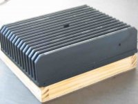
Observe this heatsink...it was not enougth to hold two channels of the Dx amplifier.
This one can dissipate 250 watts of heat...means 2 amplifier of aprox. two 85 watts RMS channels continuously driven...non distorted, sinusoidal signal.
Dx amplifier, both channels driven into 4 ohms may reach much more than 300 watts of heat to be dissipated.
this attached heatsink is 250 watts when two Dx channels will produce more than 300 watts of heat.... i have already measured 338 watts of consumption.
This was tested and proved not good!
Dimensions are around 20 by 18 centimeters, and fins have 6 to 8 centimeters tall....more or less.
The attached heatsink is not enougth to be used with 2 channels of Dx amplifiers driving loads around 4 ohms (nominal impedance)...under continuous steady tone... sinusoidal and not distorted full power.
regards,
Carlos
Attachments
All calculations are based into a very simple reality tested.
" A piece of aluminium squared, having 10 centimeters each side, thickness being 2 milimeters... this will be enougth to be used as heatsink to an amplifier that will be producing 10 watts RMS of clean audio, undistorted and continuous producing sinusoidal waves "
The position is very important..this is the position used during tests...observe the attached image.
Than...calculation goes supported by that sittuation easy to test in your home.
Multiply in cross shape and you will obtain the value of "X"
Observe the sketch and be happy,
regards,
Carlos
.................................................................................................................
Yes dear moderators
I am wasting band width...i know that, and i am sorry to feel myself forced to do this way.
The explanation i can give is that people do not read the forum thread entirely...they say that is too much long... the heatsink explication was already made...but....as they do not read, i have to post once more and than will be in front of their faces.
You could watch namex complaining that his amplifier was too much hot...heatsink plays a good part into this game..not only construction errors or misadjustment...not fair not to move reading those things... i feel myself bothered as someone that has fleas inside the pants...i have to move!
regards,
Carlos
Attachments
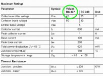
Graham Maynard observed that BC337 is not good to work into this voltage
I do not know how they did...maybe old factory here, in Brazil, was providing BC337 units with a higher (real) voltage capacity.
From Colector to Emitter, the voltage swing can reach 20 Volts (RMS) undistorted....this means danger to a transistor that can hold only 45 volts.
It seems, if someone decide to construct the brazilian unit i have published, that they replace the VAS by a bigger voltage transistor...BD139 will fit.
regards,
Carlos
Attachments
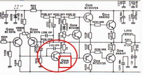
Dx amplifier has no problems, as in this position it has already a BD139
See the attached diagram...it is showing a BC337.
I do not know how they did that...or why they did that...i can imagine that the used supply had not 35 volts, or special transistors used.
regards,
Carlos
See the attached diagram...it is showing a BC337.
I do not know how they did that...or why they did that...i can imagine that the used supply had not 35 volts, or special transistors used.
regards,
Carlos
Attachments
Hi everyone!
First of all, thanks everybody for the help! And I really mean it!
That evening I decided to replace all transistors and capacitors, bias etc - practically to make a "new" board...
The fun part is that it was working, but with +-9v in base of the SC/SA!... Of course it was very heat!!!
The problem with this board (with the pieces replaced) was that the supply cable (underneath) was touching a resistor end - a short! - as
was discovered by charlie_fd... my mistake!!! (and a lesson - take it
easy, there's no hurry!....)
The voltages in the diagram help a lot!!!
Thanks everyone!
Updates:
- yesterday I replaced R10 on both boards with "matched" resistors
- with the osciloscope, we have identified a little reduction in highs -
I mounted 0,022mF on both R10
- I replaced the 220uF on rails with 470uf
What's next:
- after Carlos did the "heating math", I have decided today to mount 2
coolers inside. The coolers will run at half speed to prevent noise and
will feature a termo-couple to start them automatically
- the struggle to find GOOD genuine SC/SA continues!...
(what about other options? MJE?...)
- I will replace the 10k pot with a 1k pot+resistor
I will keep you close informed with the evolution of the project.
It wasn't yet connected to the "real speakers", so I don't know yet
how it stands again other amplifiers...
P.S. Right now, the bias is still at 600. Too low?...
Very good...you are debugging your board..or Usernamex board
Well...you seem to be so close to him, that sometimes i confuse if the one is Usernamex or Charlie_fd.
Check voltages from base to emitter...observe the drivers and output voltages.... will be a good idea if they will remain from 520 to 590 milivolts...this way you will be able to "evaluate" if your biasing point adjusted is good enougth or not.
Follow your experience and check VBE voltages...they use to show us when things are wrong.
Those 9 volts...hehe.... was a big problem into the VBE multiplier....or something around the bootstrapp.
Well...strange voltages, i normally found them when i had invert supply polarities or components.
regards,
Carlos
Since we worked together, the confusion is ok...no problem at all
Now that you mention the voltages, here are my observations:
- the voltages are not stable before 3 minutes: bias and DC
I suppose it is normal
- the voltages, compared to the ones in the diagram are "comparable",
but not that close... For example: 1.1V instead of 1.27V and so on...
- the + wire was touching the 2,7k resistor - this was the mistake
That is rigth
2K7 belongs to the bootstrapp...in it's left side we have 19 volts (around that)
Differences in voltage are very normal...under plus and minus 10 percent..depends on zilion factors.
When difference is bigger than plus 20 percent and less 20 percent we have already some suspections.
Observe your face.... you are a beautifull creation of this Universe... a wonderfull bio machine.....but perceive that left side is a little different than your own rigth side.
Relax..do not find the perfection too hard...you will not find it in this world and will be very frustrated...accept that things are not perfect.
I would like you to read your mail, the one you told the defects...very good, detailed and large.
Could you make the same size when talking about qualities in near future... also details..also large?...positive things also deserve good attention.
Carlos
Re: Dx amplifier has no problems, as in this position it has already a BD139
Ideally Vce0 should exceed the highest rail to rail voltage the amp will see.
These transistors survive because they rarely have much more than single rail to ground voltage across them and then only for the duration of the transient peak. When a manufacturer specifies a maximum voltage he is guaranteeing that most transistors will survive when operated within specification.
That is very different from predicting how soon they will fail if taken beyond the limits of the specification.
The bootstrapped VAS will see slightly less than rail to rail and I suggest that Vce0>=90% of rail to rail will probably survive most of the time when device tolerance is taken into account. But I would try for Vce0>=110% of rail to rail to avoid catastrophy.
destroyer X said:
I do not know how they did...maybe old factory here, in Brazil, was providing BC337 units with a higher (real) voltage capacity.
From Colector to Emitter, the voltage swing can reach 20 Volts (RMS) undistorted....this means danger to a transistor that can hold only 45 volts.
It seems, if someone decide to construct the brazilian unit i have published, that they replace the VAS by a bigger voltage transistor...BD139 will fit.
regards,
Carlos
q206 and q210 both have the same voltage requirement.destroyer X said:
See the attached diagram...it is showing a BC337.
I do not know how they did that...or why they did that...i can imagine that the used supply had not 35 volts, or special transistors used.
Ideally Vce0 should exceed the highest rail to rail voltage the amp will see.
These transistors survive because they rarely have much more than single rail to ground voltage across them and then only for the duration of the transient peak. When a manufacturer specifies a maximum voltage he is guaranteeing that most transistors will survive when operated within specification.
That is very different from predicting how soon they will fail if taken beyond the limits of the specification.
The bootstrapped VAS will see slightly less than rail to rail and I suggest that Vce0>=90% of rail to rail will probably survive most of the time when device tolerance is taken into account. But I would try for Vce0>=110% of rail to rail to avoid catastrophy.
- Status
- Not open for further replies.
- Home
- Amplifiers
- Solid State
- Destroyer x Amplifier...Dx amp...my amplifier