Ok, coming back with new info...
1. One board in working fine (600mV)... but it is hot like hell!....
2. Second board not working, no matter what I do:
- a couple of SC5200 and SA1943 burnt
- replaced all transistors two times
- reviewed all connections etc etc... nothing!
To be specific, the behavior is:
- 17V DC speaker output
- bias not working
- after transistors replaced, hard oscillation...
- after bias adjust and transistor replaced one more time, again 17V DC on speakers...
- replaced again transistors (every time with new ones)...nothing!
- checked all resistors etc
I do not know what to do anymore!... I mean, it is normal for the
schematic to be so unstable? (I suspect everything comes from
the fact that the schematic is very prone to oscillation - am I wrong?
Notes:
- I used PCB from the site
- both PCB assembled THE SAME WAY - I have checked this many-many time - they are twins!
- all components from Farnell, including expensive capacitors etc
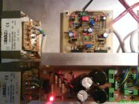
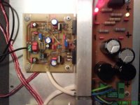
Pictures will be attached, so you can take a look...
Other things:
- this schematic has no protection at all?... I have used 1.6A fuses
and I still have enough power in speakers to blow any tweeter!
- once adjusted, the bias "likes" to be adjusted every day?...
because I have experienced many variations from day to day,
including the board which works fine...
- the temperature is SO HIGH on radiators! I have other
50W amplifiers but they do not run so hot! Not at all!
It looks like the bias should be 100 to stay on the safe side? Correct?
P.S. I have not managed yet to take a listening test... Even though
I have a working board, the crazy behavior encountered every day
for more than two weeks makes me scared to put it on
"real" speakers...
Now, has anybody from diyaudio managed to make it working,
except for Carlos and Greg? Please, have you encountered
problems? Any suggestion could be useful! (I will give one
more shot this week before giving up for good...)
Thanks!
1. One board in working fine (600mV)... but it is hot like hell!....
2. Second board not working, no matter what I do:
- a couple of SC5200 and SA1943 burnt
- replaced all transistors two times
- reviewed all connections etc etc... nothing!
To be specific, the behavior is:
- 17V DC speaker output
- bias not working
- after transistors replaced, hard oscillation...
- after bias adjust and transistor replaced one more time, again 17V DC on speakers...
- replaced again transistors (every time with new ones)...nothing!
- checked all resistors etc
I do not know what to do anymore!... I mean, it is normal for the
schematic to be so unstable? (I suspect everything comes from
the fact that the schematic is very prone to oscillation - am I wrong?
Notes:
- I used PCB from the site
- both PCB assembled THE SAME WAY - I have checked this many-many time - they are twins!
- all components from Farnell, including expensive capacitors etc
Pictures will be attached, so you can take a look...
Other things:
- this schematic has no protection at all?... I have used 1.6A fuses
and I still have enough power in speakers to blow any tweeter!
- once adjusted, the bias "likes" to be adjusted every day?...
because I have experienced many variations from day to day,
including the board which works fine...
- the temperature is SO HIGH on radiators! I have other
50W amplifiers but they do not run so hot! Not at all!
It looks like the bias should be 100 to stay on the safe side? Correct?
P.S. I have not managed yet to take a listening test... Even though
I have a working board, the crazy behavior encountered every day
for more than two weeks makes me scared to put it on
"real" speakers...
Now, has anybody from diyaudio managed to make it working,
except for Carlos and Greg? Please, have you encountered
problems? Any suggestion could be useful! (I will give one
more shot this week before giving up for good...)
Thanks!
Attachments

Hi, roender!
(I know from hi-fi.. - )
Well...
1. Of course I'm not sure! ... but my reserves of SC/SA are not
from only one source, so I exclude the possibility that they all are
troublemakers...
2. For drivers, I have tried:
TIP41C and TIP42C
TIP41G and TIP 42G
(all from Farnell)
I do not believe that the problems are related to SC/SA...
As long as DC is FLOWING without them...
One problem is that the schematic of DX does not contain "check points"... so it's quite hard to do some checks...
For example, the indicated 184mV is what????
(IT IS NOT to the ground, for sure!)
After working so extensively on DX, my firm belief is that it is very
prone to oscillations...
Also, I have not yet posted some other
experiences I had, like PCB working FINE with 10ohm/10W on rails
and crashing immediately after removing the resistors...
Also, the idea of playing around with 100pf from ground to every
transistor it does not make me happy at all...
What I hope is that someone with very good electronics
knowledge will take a look at the schematic and tell me exactly
what is to be done to remove oscillations...
As you can see from the pictures, the assembly was done "by the book"...
An error is excluded! (I know the easy way is to say "check
again", but without some "validated" check points, I won't even try for the
200th time again ...)
Thanks.
P.S. One board is working, like I said before (but it is unusable,
due to the fact that is running SO VERY HOT - but let's suppose that
this can be solved lowering the bias from 800 to 100, for example)
(I know from hi-fi..
- )Well...
1. Of course I'm not sure!
... but my reserves of SC/SA are notfrom only one source, so I exclude the possibility that they all are
troublemakers...
2. For drivers, I have tried:
TIP41C and TIP42C
TIP41G and TIP 42G
(all from Farnell)
I do not believe that the problems are related to SC/SA...
As long as DC is FLOWING without them...
One problem is that the schematic of DX does not contain "check points"... so it's quite hard to do some checks...
For example, the indicated 184mV is what????
(IT IS NOT to the ground, for sure!)
After working so extensively on DX, my firm belief is that it is very
prone to oscillations...
Also, I have not yet posted some other
experiences I had, like PCB working FINE with 10ohm/10W on rails
and crashing immediately after removing the resistors...
Also, the idea of playing around with 100pf from ground to every
transistor it does not make me happy at all...
What I hope is that someone with very good electronics
knowledge will take a look at the schematic and tell me exactly
what is to be done to remove oscillations...
As you can see from the pictures, the assembly was done "by the book"...
An error is excluded! (I know the easy way is to say "check
again", but without some "validated" check points, I won't even try for the
200th time again ...)
Thanks.
P.S. One board is working, like I said before (but it is unusable,
due to the fact that is running SO VERY HOT - but let's suppose that
this can be solved lowering the bias from 800 to 100, for example)
I feel very sad that you are still giving up Usernamex.
A pitty that you will give a shot.
Do you think Klaas, Nordic and many others are lying about the amplifier?
You do not want to play with 100 picofarads.
Well....if you are giving up...i hope, after death, that you buried the unit with respect..as during the life you are not demonstrating respect to the unit.
One board is fine.... what this tells you?
Amplifier made for good sonics uses low capacity values, not to muffle the sonics...not to disturb...of course i could make it good to the thousand constructors never find a problem...but will result into a mediocre amplifier alike hundreds of others.
Output, beeing fake, need capacitor from base to emitter.
Drivers, having gain above 120 will need capacitors too, as the final gain may be too much big...also the fake output ones have good gain...above 130 of gain (dc gain)...this may be a problem.
Are you using long wires?..... if using long wires try a coil in series..you can have HF.... also try to disconnect your zobel, as it may be tuning you speaker wires...helping oscilation in the place to block them.
Maybe you are giving up too much early without try with some forum folks assistance..too much desperated and will be ashamed when discover the "guilty" one...will have to apologize...better to be calm..let the amplifier in peace for a weak and try once more...this way, emotions will under control and you will not waste 12 gauge cartridges and parts (hehe...i like that..but not against Dx amplifier!)
Amplifiers are "low frequency oscilators" by definition..the good ones, nice sounding ones, are working into the threshold of oscilation.... i am happy that this sometimes happens...this is a good sign...i am in the threshold, probably, to some parts and arrangements.
Negative to be easy to oscilate..i have to place my fingers from the input to output, and only the mains frequency captured by my body is beeing amplified...no radio frequency..nothing.
It is not very easy to make it oscilate, the prototype and the ones i have made.... we have to supress the Miller capacitor (27pf) and the feedback capacitor (27pf) to start some unstability.
The board was checked by me and Greg..also Klaas....no problems.
Maybe you gain is very big..good selected input transistors...try a 220n capacitor from the junction R7 with R1...one extreme into the junction and other to the ground.
regards,
Carlos
usernamex,
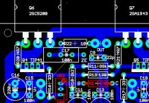
Remove c9 or replace it with 3pF
or/and
Increase C14 to 10-12pF
Also, check the voltage droped over R19, R20, R21, R15, R18.
http://www.diyaudio.com/forums/attachment.php?s=&postid=1171121&stamp=1175194354
I think that your amp suffer from HF oscillation which lead to cross conduction in output transistors
DX Amplifier
The circuit just posted does not show the VBE multiplier.
The fact that one of the modules is drifting all over the place, suggests that the VBE multiplier is either not installed ,or incorrectly fitted. I suggest that you check Greg Erskines website for the current schematic.
Regards
SandyK
The circuit just posted does not show the VBE multiplier.
The fact that one of the modules is drifting all over the place, suggests that the VBE multiplier is either not installed ,or incorrectly fitted. I suggest that you check Greg Erskines website for the current schematic.
Regards
SandyK
The schematic Roender show is not the last one.
The updated schematic is in the home page.
http://users.tpg.com.au/users/gerskine/dxamp/
You can have this adress clicking the www button.
The Miller capacitor is standard as 22 picofarads, but you can increase to 27, or 33 or 47 picofarads if perceive this as a need.
The remotion or the feedback capacitor, normally start oscilations.
But give a try there...why not, as it is already oscilating if i could understand namex correctly.
Bias not working is easy to debug...or wires are inverted, soldered wrong place, the transistor mounted inverted, or connection not made related resistances and the base....trimpot burned or broken...well...errors for sure.
regards,
Carlos
Attachments
One problem is that people do not use to read the thread.
You could see Roender suggesting old schematic.... and we have already updaded that...and many posts were made about that..with the big Attention written over the post!.
If Namex was using that schematic, the old one, and using the VBE multiplier....well, he may have problems...also double bias control is possible in that case...people can let the old bias control in the board when the correct is to remove it from the board..only the VBE multiplier will work.... Usernamex board seems to be normal, say... he did not have made this error.... this is only a possibility of error..i am happy this did not happened with Usernamex.
The old schematic shows the old resistance bias control...the new one uses VBE multiplier.
Of course..those old resistances...the fixed resistance and the trimpot have to be removed from the board...the adjustment goes to the VBE multiplier board not to have too much or long wires connected to the base.
I do not think that usernamex keept the VR2 and R14, as they were said as obsolete.... also i do not think he could left those things under the boards...this is only to remember future constructors.
regards,
Carlos
Attachments
Dear Carlos, don't get me wrong but the thread is so long and with so many non technical stuff inside that it's problematic to one be updated with all the changes. Maybe it is a good idea to edit first post and put in it the updated DXamplifier schematic.
Anyway, all suggested actions in my last post are valid
Kind regards,
Mihai
Anyway, all suggested actions in my last post are valid
Kind regards,
Mihai
Negative Roender, not valid to show the old schematic.
As we have a home page.
The need to read a thread is obvious... to know the evolution and all discussions we had about.... but landing now a days and watching the home page only, will work too..... but import old data will not be the best option.
Your suggestions of the increase of the Miller were already made in the updated schematic.... so...not a modification, this is already fixed as standard to the Dx amplifier.
Not reading, people will be out of the update schematic as you were.
Do not try to twist the reality to support yourself....not valid!
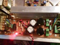
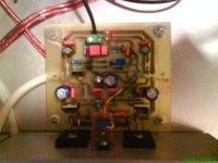
I thank you by the good intention to support your friend and our thread....but the schematic suggested was not the one we are using now a days...you can see that Usernamex amplifier is using a VBE multiplier attached to the heatsink
You know what i mean for sure, to increase a capacitor, based to an old schematic you have re invented the solution we already had found and included into the new schematic...made to make the amplifier more stable when facing different transistors than the suggested ones.
regards,
Carlos
As we have a home page.
The need to read a thread is obvious... to know the evolution and all discussions we had about.... but landing now a days and watching the home page only, will work too..... but import old data will not be the best option.
Your suggestions of the increase of the Miller were already made in the updated schematic.... so...not a modification, this is already fixed as standard to the Dx amplifier.
Not reading, people will be out of the update schematic as you were.
Do not try to twist the reality to support yourself....not valid!
I thank you by the good intention to support your friend and our thread....but the schematic suggested was not the one we are using now a days...you can see that Usernamex amplifier is using a VBE multiplier attached to the heatsink
You know what i mean for sure, to increase a capacitor, based to an old schematic you have re invented the solution we already had found and included into the new schematic...made to make the amplifier more stable when facing different transistors than the suggested ones.
regards,
Carlos
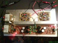
usernamex said:Board with problem:
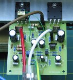
hi usernamex,
Is there an earth link on the right hand side? It a little hard to see how you have wired up your power, so please double check.
On the schematic, most of the test voltages are near nodes. The value is relative to ground and on my amp the voltages are close. My rails are a few volts higher so kept that in mod. The 184mV is a mystery to me. Carlos will have to answer that one. I'll make it clearer once I know.
I have built 2 amps so far, following the information on the web site closely. Both amps work without oscillations or overheating. I set my bias to 800mV across protection resistor but will increase it as the amp is only slightly warm after days of playing.
I used 2 amp fuses while testing but have increased them to 3.15 amp.
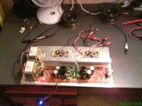
I have attached a picture of one of mine. The brown wire is output to speaker post, red is positive and white negative and the green/yellow going to star earth.
Note: I used BC556 instead of 2N5401 on the differential input, so they are reversed and C14 is 27pF, everything else is standard.
regards
Attachments
- Status
- Not open for further replies.
- Home
- Amplifiers
- Solid State
- Destroyer x Amplifier...Dx amp...my amplifier