No need to apologize nephew Roender...be happy
Greg...those milivolts indication... 184 or something around that are my mistake...the correct voltage over those resistances are 70 milivolts or something around that.
We had double..so...i made the confusion to add both voltages...each 100 ohms resistance voltage.... and the feedback one has sligtly bigger current into the colector rail too.
Please, delete my error from the schematic...as i think that voltages referenced to the ground are more correct and more standard to provide folks.
And this one was WRONG...sorry folks...i am human...my error.
regards,
Carlos
Attachments


Fine, thanks Mr Erskine.
Now that strange will be deleted and will not bother us anymore.
We will have to wait some hours, as Greg is busy and tomorrow he may delete those milivolts .
They were the voltage developed over those resistances.... the correct value is around 60 milivolts...as 600 microamperes are circulating into each transistor colector to emitter circuit.
Not a very usefull information that one..shows that you have the needed voltage drop over those resistances, prove that current are circulating from colector to emitter..also the real measurement made there allow you to conclude the current value in microamperes that are really circulating.
regards,
Carlos
Hey Carlos, you don't have to call me Mr. It's not used between friends. I'm just trying to think when Mr is used in Australia, maybe kids addressing their teacher at school, it sort of has a connotation of someone being superior, which we know is not possible.  Maybe used at very formal occasions like weddings or government meetings.
regards
Maybe used at very formal occasions like weddings or government meetings.regards
Re: Fine, thanks Mr Erskine.
Actualy, I was reading arround 600mV in that spot not 60mV ...
destroyer X said:....
They were the voltage developed over those resistances.... the correct value is around 60 milivolts...as 600 microamperes are circulating into each transistor colector to emitter circuit.
....
[/B]
Actualy, I was reading arround 600mV in that spot not 60mV ...
Same here, Greg. I only use Mr. when adressing old people, for whom i have great respect.
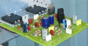
My DX using Greg's pcb is running stable and fine now for about two months.
Driving 4-8 ohms loudspeakers, using different pre-amps.
Using ugly high-capacitance ls-cables for bi-wiring.
I'm measuring 58 millivolts across 100r resistors (NOT referenced to ground) , looks fine.
Best regards,
Klaas
My DX using Greg's pcb is running stable and fine now for about two months.
Driving 4-8 ohms loudspeakers, using different pre-amps.
Using ugly high-capacitance ls-cables for bi-wiring.
I'm measuring 58 millivolts across 100r resistors (NOT referenced to ground) , looks fine.
Best regards,
Klaas
Yes guys.... so...you do not use Mr....no problem.
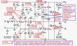
I am attaching the schematic showing voltages in red.
Those voltages were obtained after the amplifier was adjusted using 100 miliamperes and the offset was adjusted to 1.3 milivolts.
No signal at the input and speaker connected into the output...a 8 ohms speaker.
The voltage was 35 plus and 35 minus.
Those voltages are not absolutelly precise...mine units are not in my home and i have used the simulator to obtain those voltages...real life may be a little different as depends of many factors....many reasons that i will be tired to describe all them here, and now.
My prototype is beeing used now to develop another amplifier...a 330 watts unit over 2 ohms.... 250 watts over 4 ohms and 130 over 8 ohms...i am already tweaking and changing things as i want more power over 2 ohms because impedance deeps some speaker has.
Every voltage you found in your Dx amplifier circuit, with errors of 20 percent plus and 20 percent minus can be understood as normal... as this happens very often.
Off course, voltages plus 20 percent into the positive rail and less 20 percent in the negative rail, compared with the voltages provide means that you need to re-adjust your offset control.
The digital multimeter had its negative probe fixed on ground....transformer ground...the center tape.... and the positive probe was used to measure.
Exception was the VBE multiplier VBE voltage...and also the voltage from point A to C
I hope this will be help.
regards,
Carlos
Attachments
Please help
I'm having a few emails that the latest schematc is not appearing. Can a few people do a check for me.
Go here: http://users.tpg.com.au/users/gerskine/dxamp/
Click on Amplifier Schematic in the table of contents, scroll down a bit, it should be dated GE20070619F, and no voltages near R4 amd R8.
Click on Contact in the table of contents, it should say "Page last updated: Wednesday, 20 June 2007".
regards
Graham Maynard said:Hi Greg,
Nice Dx-amp construction.
The circuit is coming up just fine here.
Both pages coming up 19th June - you are ahead of us.
Cheers ........ Graham.
Graham,
Thanks, but the on the Contact page it should read 20 June 2007 (it's actually hard coded in the html page, not javascript). The "Building instructions" should now include a schematic with test voltages. Can you "refresh" or "clear cache". It must be a local cache, proxy or it might just take time for the latest version to become available.
sandyK,
I hope the Vbe multiplier has been there for a few weeks.
regards
Greg Erskine said:Please help
I'm having a few emails that the latest schematc is not appearing. Can a few people do a check for me.
Go here: http://users.tpg.com.au/users/gerskine/dxamp/
Click on Amplifier Schematic in the table of contents, scroll down a bit, it should be dated GE20070619F, and no voltages near R4 amd R8.
Click on Contact in the table of contents, it should say "Page last updated: Wednesday, 20 June 2007".
regards
Hello
It's ok for me, I can see the dated GE20070619F and the updated: Wednesday, 20 June 2007
Gaetan
Observe folks... i have just re-invented the powder without smoke
This is not a DX amplifier....but it is a very close "cousin"...as all bootstrapped designs belongs to the same family.
Bootstrapped designs exists since the seventies... this one show was made in 1980.... around 10 thousands were sold!
I am showing you an schematic of a Brazilian Receiver, the Brand as CCE and the model was SR3220.
You see, that this kind of circuit was old and used hardly in many countries including mine.... reliable it is because of the topologie....hard to produce problems and sound very nice.
Mine one, Dx amplifier, was calculated since the first part, following my own beliefs...also parts included or removed were made during audition, when the amplifier was tuned for sonics.
It is nothing new, or extraordinary...it is simple, cheap and a very nice sounding unit.
Proved for more than 35 years, used by all Japanese industries, also used for Guitar and Bass Amplifiers (modified, of course)...and i could se some Professional units using this same circuit topologie.
If the amplifier present problems.... check your amplifier 3, 4 or "N" times..as this was constructed in millions units...Yamaha, Kenwood, Sony, JVC, Marantz also...all them have used...this circuit can be more easy to oscilate as it is not "mufled"...not hardly protected against possible oscilations...made this way to sound fine...if we start to increase capacitors, or to include capacitors in other transistors..the sound will result mediocre...will result common...normal...standard...nothing that audiophile may apreciate.
regards,
Carlos
Attachments
- Status
- Not open for further replies.
- Home
- Amplifiers
- Solid State
- Destroyer x Amplifier...Dx amp...my amplifier