Thanks Carlos, thats nice, and good pictures
But Im not that fast
Printer well, Im running out of paper
  fortunately I have a good friend taking care of my computer
Im on to digikey
Very nice
Project is saved
But man, these things takes time

But Im not that fast
Printer
well, Im running out of paper fortunately I have a good friend taking care of my computer Im on to digikey
Very nice
Project is saved
But man, these things takes time
Relax... do not need to be fast..also you do not need even to build
You have helped me.... i will open a Dx Amplifier builder thread...because those images i have selected to you are needed to the ones wants to build.
I see that folks does not want to read the whole thread..so... i will prepare something smaller for them.. as suggested by Chris Bridges (Anatech) and by Todd Johnson.
regards,
Carlos
Dx amp builders thread
Very good idea Carlos
Very helpful
I will wait posting there till I have more done
Well, Im having fun
I think fore starters I will make a small board just with these components, input/dc adjust/TIP42
Ehh, and small supply caps etc
Mounted close to 2SA1943
Some resistors and caps hardwired
Groundplane wil be thin copper plate
btw, I couldnt do none of this without looking at printouts from Gregs site, and your help
Hope you like it 🙂
Attachments
Sorry Carlos i`m late to post the video.
Hi Dx,
Fuhhhh.... i`m coming now, uploading the video as i`m promise, sorry i`m late to post the video.
Ok now this Dx Amp now run with +42 0 -42 VDC at 15 Amp. Testing on 8" Mohawk 120 wrms rated and 240 wrms peak. Testing with Bass i love you, about the sound from my camera i`m sorry to say that the camera mic can make an original sound really, the sound is wonderful maybe its too close so the sound more blur at this point.
I`ve testing it today, actually every day i`m using this amp and throwing my Aiwa and Sony amp into the box because its not good as DX amp 😀. The speaker cone start warm at 1/3 volume and the cone is touch at the bottom so i dont want to blew it. LOL 😀. Testing on Alpine 10" 300 wrms at 8 ohm is ok with 3/4 volume sound is fine and power amp also fine 😀.
So Dx please wait until uploading is finish. 😀
Best Regards,
Azmi.
tinitus said:Dx amp builders thread
Very good idea Carlos
Very helpful
I will wait posting there till I have more done
Well, Im having fun
I think fore starters I will make a small board just with these components, input/dc adjust/TIP42
Ehh, and small supply caps etc
Mounted close to 2SA1943
Some resistors and caps hardwired
Groundplane wil be thin copper plate
btw, I couldnt do none of this without looking at printouts from Gregs site, and your help
Hope you like it 🙂
Dont worry tinitus, we will help you and do assamble the parts when you`ve finish the baord, if you have any thing to ask then please... we will try to guide you, dont plug it on yet if you`ve finish it, please post the picture here first and lets Uncle Carlos review it for the first time 😀. You`ll not disappointed when it works. 😀
Here is the Video.
Hi Dx,
Here is the video i`ve finish it, i`ll take another video that will show the amp with the speaker, actually the amp is finish assamble and i`ll open it to show here.
http://www.youtube.com/watch?v=o_f1sIp3aUc
Best regards,
Azmi.
Hi Dx,
Here is the video i`ve finish it, i`ll take another video that will show the amp with the speaker, actually the amp is finish assamble and i`ll open it to show here.
http://www.youtube.com/watch?v=o_f1sIp3aUc
Best regards,
Azmi.
Many thanks Norazmi..... but i felt something strange
with your speaker cone movement..seems off set is not stable....maybe capacitors into the long tail..there we cannot install big ones.... 100n to the zener and 2N2 in between the resistances (fixed and off set adjusting trimpot)
I have this same music here and i will test it here.
Thank you very much.
regards,
Carlos
Attachments
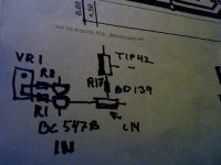
This is the off set adjustment trimpot
in between two resistances, it is a very good idea to have a capacitor to ground to avoid unstabilities...in our case, we need them very small in value, to be charged very fast avoiding the power on thump.
regards,
Carlos
in between two resistances, it is a very good idea to have a capacitor to ground to avoid unstabilities...in our case, we need them very small in value, to be charged very fast avoiding the power on thump.
regards,
Carlos
Attachments

Re: This is the off set adjustment trimpot
Ooo, Okay i`ll put it 2200 pf like your suggestion.
Dx, i`m plan to use +64 0 -64 maybe next week and i`ll produce 2 new Dx Amp Board, i`m prefer to use 3 pair output transistor per channel or maybe 4 pair?, Toshiba 1302 and 3281, what do you think? i`ll change BD139 with MJE13005 and tip41c/42c with mje15032/33 what do you think?
SO what about VR2? its 1k trimpot there, should i change it to 2k? or parallel it with 1k trimpot plus 500 ohm resistor? Previous one will be running at +- 42 vdc and stable so my younger brother ask me he want that amp for home theater system so actually its hard for me to give it to him but he beg me.
SO i need new one, my plan to run it with +- 64 VDC since i`ve that toroid ferrite already running it with offline smps, we can make any ampere we like with that thing so its flexible, depends on trafo and wire coil to carry how many wattage we want. About the component and other thingy to make this, its because i`ve friend who has working as tv&radio repair here and another one is working for motor coils winding etc.... so i can get the stuff very cheap sometimes free FOC 😀 and at the same time they want the DX AMP too LOL 😀
also to TAJ, you`re good friend with uncle Carlos i think. Thanx for the Logo Bro 😀
Best regards,
Azmi.
destroyer X said:
in between two resistances, it is a very good idea to have a capacitor to ground to avoid unstabilities...in our case, we need them very small in value, to be charged very fast avoiding the power on thump.
regards,
Carlos
Ooo, Okay i`ll put it 2200 pf like your suggestion.
Dx, i`m plan to use +64 0 -64 maybe next week and i`ll produce 2 new Dx Amp Board, i`m prefer to use 3 pair output transistor per channel or maybe 4 pair?, Toshiba 1302 and 3281, what do you think? i`ll change BD139 with MJE13005 and tip41c/42c with mje15032/33 what do you think?
SO what about VR2? its 1k trimpot there, should i change it to 2k? or parallel it with 1k trimpot plus 500 ohm resistor? Previous one will be running at +- 42 vdc and stable so my younger brother ask me he want that amp for home theater system so actually its hard for me to give it to him but he beg me.
SO i need new one, my plan to run it with +- 64 VDC since i`ve that toroid ferrite already running it with offline smps, we can make any ampere we like with that thing so its flexible, depends on trafo and wire coil to carry how many wattage we want. About the component and other thingy to make this, its because i`ve friend who has working as tv&radio repair here and another one is working for motor coils winding etc.... so i can get the stuff very cheap sometimes free FOC 😀 and at the same time they want the DX AMP too LOL 😀
also to TAJ, you`re good friend with uncle Carlos i think. Thanx for the Logo Bro 😀
Best regards,
Azmi.
Will prepare a 64 volts schematic for you
Untested one....soon i will post a pdf here in this thread.
regards,
Carlos
Untested one....soon i will post a pdf here in this thread.
regards,
Carlos
Very strong this one Norazmi.... maybe 440 watts RMS into 4 ohms
More than 220 Watts into 8 ohms.
the output is bigger than 42 volts RMS.... into 8 ohms you gonna need 15000uf each rail....and into 4 ohms you gonna need 25000uf each rail.
Hummmmm...very expensive!
I think three pairs will be good to 8 ohms...but to use 4 ohms will be a good idea to go to 6 pairs.
Heatsink will be enormous...and each amplifier will suck 5.5 amperes each rail... total of 11 amperes to each channel...... huge...very huge transformer....better to use two 700 watts transformers.
regards,
Carlos
Attachments
Very nice clean schematic. Very professional.
Does the VAS need such a huge transistor?
..Todd
Does the VAS need such a huge transistor?
..Todd
No!... the VAS does not need such a huge transistor
I just put this one in place into the simulator..but lower power units will be so good, or better.
Important into this position is capacitance from base to emitter (smallest possible)....tolerance to rail to rail swing voltage... and something alike 5 watts will be excelent.
The intention is to show we CAN use big ones..but this does not means we should.
regards,
Carlos
C12 is almost a rail to rail condenser... to be safe
use at least 50 Volts condenser there..because negative side has variable voltage from the output line.... when amplifier swings to minus 26 volts alternated you gonna have 45 volts into this condenser terminals (around twenty into the positive side.. then add -26 volts alternated) .. so.... to be more and more safe, then use 63 volts.
But that other one is a hell difficult answer Tinitus.
Voltage there is low.... Dc voltage is low, but AC voltage there is high...so... another 63 volts condenser is a good idea.
If you mean voltage when you say size, then you already have the answer.
If size is how big it is..well...you can use the one you have..big or small,.
regards,
Carlos
..............................................................
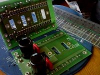
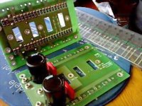
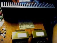
Very nice power output boards Tinitus...this serves to many amplifiers..have to build differential, VAS and drivers in one board and run wires to those power boards.....nice!
use at least 50 Volts condenser there..because negative side has variable voltage from the output line.... when amplifier swings to minus 26 volts alternated you gonna have 45 volts into this condenser terminals (around twenty into the positive side.. then add -26 volts alternated) .. so.... to be more and more safe, then use 63 volts.
But that other one is a hell difficult answer Tinitus.
Voltage there is low.... Dc voltage is low, but AC voltage there is high...so... another 63 volts condenser is a good idea.
If you mean voltage when you say size, then you already have the answer.
If size is how big it is..well...you can use the one you have..big or small,.
regards,
Carlos
..............................................................
Very nice power output boards Tinitus...this serves to many amplifiers..have to build differential, VAS and drivers in one board and run wires to those power boards.....nice!
Attachments
Perfect answer, thanks
Just found out why I found resistors missing on my printed BOM
Lack of paper space
Seems I still have printer problems
Those output boards
Well, they were made fore the amp modules I am listening to know
But I changed my mind and thought I would try a small amp, fore a change
I have no regrets
But cant get myself to sell those output boards, with matched On-semis
Im not ready fore switchmode and class-D
If I get a change to get it working, it will probably be fore woofer use only
Still working on my own DX board layout
Nearly gave up, but im getting there now

Re: No!... the VAS does not need such a huge transistor
I see. Good lesson, teacher. Thanks.
destroyer X said:The intention is to show we CAN use big ones..but this does not means we should.
I see. Good lesson, teacher. Thanks.
For years long i had no good parts to assemble my amplifiers
sometimes i could not have a good transistor to the VAS position.. sometime the VAS current was too much high and the BD139 (my standard one to VAS position to 35 volts supplies) operated too much hot.... then i tried big transistor into that position and i could see they work fine..also into the driver position...big ones works fine there too.
I have tried the big ones (PNP, as i have a lot, without complementary) in the place of diodes and resulted great.
Also i have tried BD139 into the differential and felt them very good too.
That sittuation i had in my life...never having a good stock of parts (now a days i already have) forced me to try those things.
They are not perfect in those strange positions..as power transistors were made to power output position dear Todd...but they work,...in an emergency.... you can install them and they will work fine.... they are not ideal, but, it is hard to perceive the difference from one compared to the other.
We perceive the board turns ugly with that monster transistor there..this is clear..we see immediattely.
regards,
Carlos
- Status
- Not open for further replies.
- Home
- Amplifiers
- Solid State
- Destroyer x Amplifier...Dx amp...my amplifier