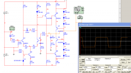
Well, comp caps wasn´t absolutely necessary as the zobel filter and comp network between diff transistors almost stabilize the circuit enough, there is a slight ringing remaining which could look like an overshoot due to saturation, but I doubt it really is saturating at this drive level - no where near maximum output voltage. However, what I find a bit odd is that the amps seems overall faster with just resistors loading the input diff stage. Can´t figure out why one slope is faster than the other just because of current sources being used instead. They should pass the about same current amounts.
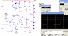
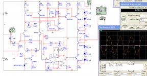
Here are two better pictures I hope, just the front end.
........
Hi Rikard,
Indeed, much much better. Thanks.
Cheers,
E.
It´s just a remaining diode from the Luxman schematics I was inspired by, and I suppose it´s there to cancel the bass-emitter drop of Q10. Probably not needed now as Q6 doesn´t have it too.
Next step would be cascoding the input diffs, but the primary goal is to use current sources as loads for the input diff stage if I can somehow make the + and -slews similar.
Next step would be cascoding the input diffs, but the primary goal is to use current sources as loads for the input diff stage if I can somehow make the + and -slews similar.
Last edited:
Hi Rikard,
You cannot put constant (i.e. fixed) current sources in series*. Remember the VAS troubles with Randy Slone's amp? You will need some form of feedback from the VAS DC current back to the current sources in order to get the right balance. See Bob Cordell's HEC amp for an example how to tackle this issue.
Cheers,
E.
* for the same reason, as everyone knows or should know, you cannot put different voltage sources in parallel.
You are probably right, I just hope I could get away with slightly less complex design, and I also like the idea of the Hawkfords cascodes.
🙂
🙂
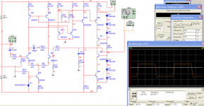
Things keep getting better! Found some more speed by tweaking the comp networks a bit. Looks like about 160 volts/us to me now. Now I just have to get rid of the DC offset.
Can´t wait for Bob´s book to arrive!
🙂
Can´t wait for Bob´s book to arrive!
🙂
Attachments

Last edited:
Things keep getting better! Found some more speed by tweaking the comp networks a bit. Looks like about 160 volts/us to me now. Now I just have to get rid of the DC offset.
Can´t wait for Bob´s book to arrive!
🙂
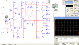
you have unbalanced input bias currents. you have the noninverting input tied to ground through a 39k resistor, and the inverting input through a 120 ohm resistor. same thing happens with op amps, offset caused by unequal bias currents at the inputs. try changing both of them to 10k, and recalculate the feedback resistor to keep the closed loop gain the same. you will also need to recalculate the values for R17 and C2.
Last edited:
Hm, not sure if that´s the real reason, I often see amps where the inverting input is driven from a fairly low impedance to keep speed up and noise down. The non inverting input should have a very high input impedance so keeping it to ground potential should not be a problem with a 39 k resistor, but you might be on to something. My guess is that something in the diff amp outputs cause the offset, which could of course be corrected with a DC servo which I intend to use anyway.
Will experiement with another config of the Hawkfords cascodes as well, and try a more conventional current mirror idea.
🙂
Will experiement with another config of the Hawkfords cascodes as well, and try a more conventional current mirror idea.
🙂
Uncle is telling you that you have mixed AC and DC coupling in your proposal.
I believe one should adopt either all DC coupled or all AC coupled.
BTW, using a DC coupled amplifier fed from a source with a DC blocking capacitor at it's output converts your DC coupled amplifier to a mixed AC/DC coupled amplifier. One of the effects of doing this with a DC blocked source will be a big jump in output offset and this comes from the input LTP seeing different voltages @+IN and -IN. You have unbalanced the LTP.
So, a DC servo is the solution? I sure wouldn´t want to omit the DC blocking cap in case the signal source would fail and put out several volts of DC.
A DC servo feeding correction voltage to one of the LTP inputs could unbalance the LTP even more.
You would have to identify where the DC servo should feed to remove the voltage error that is causing the problem, not by adding in a further error.
You would have to identify where the DC servo should feed to remove the voltage error that is causing the problem, not by adding in a further error.
If you want DC coupled, then I believe you need DC detect and input muting and output isolation to give you a safe system.So, a DC servo is the solution? I sure wouldn't want to omit the DC blocking cap in case the signal source would fail and put out several volts of DC.
Simply adding an input cap and a servo is not enough in my view.
i have noticed a lot of DCservo designs couple the output of an op amp (theoretically a zero impedance output) through a resistor equal to the resistor from the noninverting input to ground, maintaining balance at the inputs to the LTP, and the servo "tweaks" the ground reference of the inverting input.
Hi,
10uF polarised with leak.
It will act like a cap//resistor. The resistor value will vary with time and temperature and voltage and time since last use and time currently operating.
I strongly suggest you use a plastic film cap. MKS, MKT are usually good enough.
10uF polarised with leak.
It will act like a cap//resistor. The resistor value will vary with time and temperature and voltage and time since last use and time currently operating.
I strongly suggest you use a plastic film cap. MKS, MKT are usually good enough.
- Status
- Not open for further replies.
- Home
- Amplifiers
- Solid State
- Designing amp with 2SJ201/2SK1530