I was referring to the version without EC.There is the entire error correction network between the VAS and OPS so I don´t understand what you mean?
I did try the VAS directly to a standard OPS with very good results too, so if the bias of the VAS transistors is cranced up to let´s say 25 mAs or so it works very well.
🙂
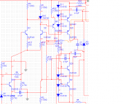
Here´s a slightly simplified VAS with a single transistor balancing the cascoded VAS output. (Q24 and Q25 are new) This way, it is still a fully differential config, but simpler. Still, the distorsion figures look really good imho, but as usual I cannot get it completely stable into capacitive loads.
Attachments
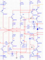
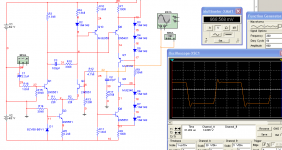
Latest updated schematics. The addition of Q24 and Q25 alone clearly reduced distorsion. What I don´t like is the tendency that odd overtones seem to consistenly remain higher than the even ones. At least in sims, but this might not be the case in real life. The fourier analysis was simmed with an 800 mV 1 kHz input.
🙂
🙂
Attachments
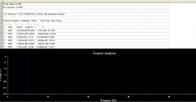
at -100db, i wouldn't complain. real life distortion will be more, but with such a good starting point, i think it will be pretty good
Might want to disconnect the zobel before pressing the THD button.
Multisim 11 just arrived -- i can't tell the difference form Multisim 10.
Multisim 11 just arrived -- i can't tell the difference form Multisim 10.
The Zobel didn´t affect distorsion. But it helped a bit with stability into capacitive loads. The output coil however proved to do the trick.
Can´t wait to finish the prototype! 🙂
Can´t wait to finish the prototype! 🙂
Any thoughts from you guys about using the new 2SK3497/2SJ618 pair from Toshiba in this design? Bob Cordell, I would appreciate any feedback from you.
🙂
🙂
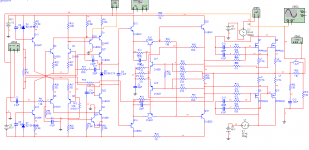
So, my "investigations" go on, and having been inspired by the Mongrel thread, and particularly the Luxman schematic mentioned there (Hawkford style cascodes), I have started simming an updated design of the amp. Basically, the same Cordell OPS is used, but a slightly modified front end is used now. I tried replacing the two resistors loading the diff amp at the input with current sources, and this lowered the distorsion quite a bit, but a drawback is that if I look at a 200 kHz square wave the upward flanks are much slower than the downward ones. Anybody who can come up with a solution for that?
Pic 2 is the current source loaded version, and Pic 1 use resistors and seems to perform brilliantly.
Comments appreciated!
🙂
Pic 2 is the current source loaded version, and Pic 1 use resistors and seems to perform brilliantly.
Comments appreciated!
🙂
Attachments
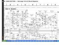
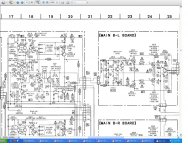
Thanks, I´ll try to make the schematics more readable and explain what happens in the front end. I know that Sony have used the Toshiba FETS for some time, I even serviced some of these amps when I worked as a technician. Good stuff for sure!
🙂
🙂
I can see all the wiring and read all the component details. I can see all the dots that show connected wiring.
The wiring is confusing, but then so are many other schematics that show complex topology.
The wiring is confusing, but then so are many other schematics that show complex topology.
True, and that should be changed. If someone don't take the effort to draw a decent schematic, then why should I take the effort to read it?.................
The wiring is confusing, but then so are many other schematics that show complex topology.
True, and that should be changed. If someone don't take the effort to draw a decent schematic, then why should I take the effort to read it?
Well, you shouldn´t if you find it too hard to read. I´ll draw the front end alone and post better pictures.
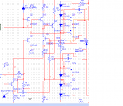
Here are two better pictures I hope, just the front end. Version one has CCS loaded diff amp outputs but suffers from uneven slew rates for positive and negative flanks. Cannot figure out why. The resistor loaded version is much more even but cannot reach as low distorsion figures.
🙂
🙂
Attachments
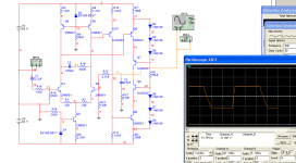
i noticed you have no compensation caps. you could "tweak" the slew rates with compensation caps. i've also seen current mirrors used, not only to linearize the diff amp, but to insure both VAS devices are driven by the same currents, which also seems to match the slew rates.
i see the first one has slew rates of 67V/uS(- slope) and 100V/uS (+ slope). these slew rates will probably be faster than you could hope of driving the amp within the audio band. the negative slope aldo looks like it has a bit of "hangover" from a device coming out of saturation. the device that's saturating is probably also the reason for the slower slewing.
i see the first one has slew rates of 67V/uS(- slope) and 100V/uS (+ slope). these slew rates will probably be faster than you could hope of driving the amp within the audio band. the negative slope aldo looks like it has a bit of "hangover" from a device coming out of saturation. the device that's saturating is probably also the reason for the slower slewing.
Last edited:
- Status
- Not open for further replies.
- Home
- Amplifiers
- Solid State
- Designing amp with 2SJ201/2SK1530