@tubesall, I have never read some many wrong, unspecified and superficial statements in few lines.
One doesn't have to follow all rules mentioned in a book, be it Crowhurst, RDH4 or Grosser. You can only pick the knowledge that suits you well. One also doesn't have to follow stereotypes.
Sure, i have, among other things, been a consultant to BBC, Philips, Thomson, just to name a few, without any knowledge. As to experience, once you have managed to have 56 years proffessional experiance on your back, like i do, you can talk about experience, before that, shut up and stop making a fool of yourself like you do now.....without having experience and knowledge to assess what he is thinking!

@gorgon53 You are misquoting now, extracting piece of text out of context. Or do you have experience in everything?
if you have experience of the subject you should know or able to find the answers to your questions. If you have no or little experience in this topic, you are not in the position to assess. That's what I meant.
Let me re-phrase it: you questioning/rejecting/doubting everything because you think you are right, smarter and experienced but you have no answer and are asking if there is a solution at the same time.
Yes, I am a fool because I tried to reply to your questions. That was a BIG mistake and total waste of my time.
Last edited:
About misquoting: that was exactly what you were doing misquoting the Fochenkov article. It suited you to back up your claim and you treated my comment as being nitpicking.@gorgon53 You are misquoting now, extracting piece of text out of context. Or do you have experience in everything?
When faced with opposition you take the route of personal attacking, showing disrespect to several members here.
You simply can not stand the idea that someone else also might be "right, smart and experienced" (to quote you...).
It is obvious that you know a lot about transformers, but you refuse to show your experience (never saw one of your transformers).
Your big problem, likely also outside this forum, is your unability to communicate constructively and respectfully.
Last edited:
Then @tubes4all, show me how you calculate or measure core loss in SE transformer in actual use, including the correct working conditions. I cannot see it.
You actually confuse core loss in gapless transformers with core loss in gapped transformer.
I have never actually seen any irrefutable technical response from you, be it either a measurement relating to specific subject or a formula. Not even a link that tis relevant to the discussion. Nothing.
If you think that my explanation is bad, it could be true and I don't care. It is still better than nothing at all or 100% wrong answer.
For your knowledge I have all sorts of transformers with all sorts of cores and I have no conflict of interest......
Here below my last buy. Again, you are wrong.
Attachments

Last edited:
Oh….you only buy transformers? So i was right, you not made any transformer yourself.
I guess you not understand what a gap dos, you still have hysteresis loss but the BH loop flattens by adding a gap, it not disappears.
If you did understand coreloss you would not choose the EI laminations. If you did understand coreloss you would be interrested in nanocrystalline cores also fo SE.
I guess you not understand what a gap dos, you still have hysteresis loss but the BH loop flattens by adding a gap, it not disappears.
If you did understand coreloss you would not choose the EI laminations. If you did understand coreloss you would be interrested in nanocrystalline cores also fo SE.
What does this mean? "you still have hysteresis loss but the BH loop flattens by adding a gap, it not disappears." It is true for every core of any material. If you never quantify and compare it to the total loss and distortions of every other type you will never know how relevant it is. The nanocrystalline or amorphous core will not get the same inductance increase with signal. Is that really an advantage? My opts above have 21H small signal and only 23H at higher level. The Hashimoto 3.5K, same impedance, has 20 and goes up to 28 H. Your favourite Tango will go up 38H. What does this mean in terms of distortion at low frequency? How can you say that the steel core is worse if you get better distortion figures at low frequency? Only solution use bigger core for the same task but then cost will be higher and still, there is no guarantee. You have to be a believer because the amplfier in the end is only one component of the stereo system, the trnasformer is component of a component! Sound can change without spending extra money. It is still questionable!
Continue guessing....
Continue guessing....
Last edited:
Marek invested in nano cores because he expects to make the finest transformers possible, otherwise he could have saved cash by buying GOSS c-cores (or M6 EI laminates at a local industrial winder).
You, 45, will not change that by bringing in your arguments, no matter the pros and cons of the different materials.
Start a new thread about "incapacity of nanocrystalline c-cores for SE output transformers" or something like that.
By the way, distortion is not such an interesting phenomenon in transformers; it is very low (until core saturation sets in of course).
Core material has always influence on final sound, and nano cores do very well in this regard.
Also don't treat amorphous and nanocrystalline the same, they differ.
@daanve, you are mistaken. I don't want to change anything. I never said that he should throw the nanocrystalline core in the bin.
I actually told him that I hope that the DC permeability graph I found in the Hitachi website, although attached to the very same core he has, is a generic one and related to smaller core of so that he will get 40H with 3000 turns.
I am not the one with absolute truth in his pocket and lauching epithets like "this is better and this is worst".
Do you want to bet that changing cathode bias electolytic capacitor with inexpensive DC-Link cap has much effect than changing the core in SE amp?
So here we are again....
The increase in induction of SiFe is because of imperfections of the core material and the lamination thickness. this is not an advance but a shortcoming of the material. Good datasheet should give you such information. The gap will limit the increase a lot btw.What does this mean? "you still have hysteresis loss but the BH loop flattens by adding a gap, it not disappears." It is true for every core of any material. If you never quantify and compare it to the total loss and distortions of every other type you will never know how relevant it is. The nanocrystalline or amorphous core will not get the same inductance increase with signal. Is that really an advantage? My opts above have 21H small signal and only 23H at higher level. The Hashimoto 3.5K, same impedance, has 20 and goes up to 28 H. Your favourite Tango will go up 38H. What does this mean in terms of distortion at low frequency? How can you say that the steel core is worse if you get better distortion figures at low frequency? Only solution use bigger core for the same task but then cost will be higher and still, there is no guarantee. You have to be a believer because the amplfier in the end is only one component of the stereo system, the trnasformer is component of a component! Sound can change without spending extra money. It is still questionable!
Continue guessing....
It’s a lie that steel has lower distortion levels at low frequencies, its a matter of design.
Why are you trolling 45?
Increased of induction? Where? If max induction is at 20Hz what would be the induction at 40Hz, 100Hz and so on????
The transformer in this thread has (ideally) 40H at 100 mA DC. Bdc is proportional to their product. This means that the 30W limit could be 27Hz. Below 27Hz Bdc will be less than Bac. However still need to check that the total induction is within saturation. Being the core cross-section 23.4 cm^2 and the number of turns 3000, the total B at 27Hz will be just over 1.1T. Just enough! Bac, where the loss happens, is about 0.54T. At 40Hz, Bac is less than 0.37T and at 100Hz is 0.27T. It has already halved. It will be less and less relevant as frequency goes up, where >90% of musical signal lives!
Roghly speaking, core loss is at worst as much as copper loss at lowest frequency for ungapped steel core transformers. You can find that in the literature. With gap, the area of the loop is easily 10-20 times smaller. Sometimes even smaller. Consdier that induction is inversely proportional to frequency and that's why it becomes a very minor issue.
This is also why comparing losses of gapped cores with zero DC induction and max AC induction at 100Hz, like in the article someone is desperately clinging to, is not relevant for the practical use in SE.
Try to make to different coils, with different gemotry and/or insulators. I can bet that it will sound different without changing the core. That is a lot more relvant than core material.
Finally, from my perspective is nothing in comparison to other non-ideal behaviors of the AMPLIFIER, including its power supply.
Please DEMONSTRATE otherwise. Not with meaningless words but with NUMBERS!
Last edited:
This happens:With gap, the area of the loop is easily 10-20 times smaller. Sometimes even smaller.
Attachments
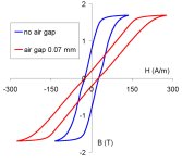
About nanocrystalline core. This is not about permability, core losses ect. but about B-H curve which nonlinearity directly affects distorsions.
Here is comparsion of B-H curves of:
- annealed cold-rolled transformer steel steel (0,3 mm)
- amorphous iron-based alloy
- nano-crystalline alloy AMAG-200S series MSTAN (russian 🙄 flat foop type nanocrystalline material)
without and with gap accordingly:
View attachment 1165524 View attachment 1165527
Histeresis loop indeed flatens with air gap as show above but final effect isn't the same. As core loss is proportional to loop AUC there is no doubt that core loss is the smallest with gapped nanocrystalline core.
That is not the practical case. In the practical case of SE amplifier, only 1 quadrant is used and Bdc>Bac ( plus, Bdc + Bac < Bsat) so the area for the AC loop is already more than 4 times smaller than that at the lowest frequency ONLY! Smaller and smaller as the frequency goes up.This happens:
0.07 mm airgap I never used it in output SE transformers except in tiny 2W transformers with primary impedance of 10-12K with small dc currents around 20mA. Easy to get with EI laminations in the form of distributed gap by interleaving the E's and I's. Hard to get with C cores with simple tools. But it actually proves my point about using an oversized core with tiny gap.....
The article linked before shows a large difference between gapless and gapped because a more appropriate gap has been used.
Last edited:
Indeed, so much less loss for nanocrystalline materials. In practice the airgap will be a lot bigger but even then 0,07mm is also very easy to do.Histeresis loop indeed flatens with air gap as show above but final effect isn't the same. As core loss is proportional to loop AUC there is no doubt that core loss is the smallest with gapped nanocrystalline core.
Btw indeed because Bdc you only use a part of the BH loop but your ironloss dos not starts at B=0T.
0.07 mm for the transformer of this thread is inappropriate. It is 0.5 mm for now. Quite a difference!
Sure a difference. Once Marek prototyped his first coil, he can experiment with airgapping. It happens that one of the advantages of using c-cores is that changing the airgap is done in minutes. Try that with EI, which have always more or less airgapping, and therefore not a defined airgap.
Especially for single projects c-cores are so much more practical.
Especially for single projects c-cores are so much more practical.
Using a standard HWR steel core 0.3 mm lamination with the same size of the nanocrystalline core of this thread, airgap would not be much different.
My first condition is to avoid permeability drop for small increase of DC current respect to nominal. Let's say the gap is for 100 mA DC current but it will be fine with 110 mA and still doing ok for 115-120mA. This is a way to maximize inductance per turn using as small as possible gap and get low copper loss, as well.
Core HWR 90/44 with 4C's and one bobbin: 2800 turns (so even a bit lower copper loss is possible, geometry and wire size being the same) with 0.5 mm airgap for 100 mA DC will result in 42-43H minimum (0.002T AC) and about 56-58H for 0.2T AC.
Total induction at 25Hz for 30W output is about 1.2T. Bdc still bigger than Bac and well below saturation, resulting in low distortion.
This doesn't need any experiment as I am selecting the correct gap on the actual curves of permeability vs H for different g values. g= airgap x mean magnetic path length. This way the permeability curves are independent of core size.
Again it is 0.5 mm. It is not 0.07 mm.
- Home
- Amplifiers
- Tubes / Valves
- Design of C-core nanocrystalline GM-70 output transformer