The discussion is (should be) about designing an OPT for SE GM70 using nanocrystalline cores....
I was merely pointing at the existence of a range of C-cores with the same dimensions as EI; you don't have to tell me that the electromagnetical properties differ....
By the way, Femag has been the first brand of c-cores I used, and proved to be the worst quality (producing an oily substance in the gap when clamping halves together because of bad impregnation).
For GOSS c-cores I'd stick to Nipponcore HiB, available in different lamination thickness and reasonable MOQ's if you know "how to...".
Maybe they gave you the worst quality because they understood that you are not an expert. I could bet on that. In fact, they do not have HiB, at least in form of C cores. They are not the same thing and they are not necessary for a high quality transformer. HiB might be necessary for you because you want to put EVERY time the minimum amount of turns as you have no idea how to optimize the high frequency performance at design stage.
Last edited:

It is relevent in terms of cost, those 100kg+ orders is nonsense.
It is also nonsens that for a give transformer size EI can be the same quality, just core losses is a factor 4 or more normally. And maybe you should look at the coreloss graphs more serious before you say that a the smaller core is the best option.
Oh, and about the BH loop, EI is also a lot worse.
Maybe you should publish some of your great results here, but i guess you will never do this but there is none.
Last edited:
@tubesall your reply shows you confusion. The correct graph is not the gapless loop from manufacturer. Core loss is precisely determined by the area inside the loop. Gapless is not the same as with airgap. Loops have also been posted earlier in this thread....
That's also the reason why exotic materials with lower loss are more useful for PP application.
That's also the reason why exotic materials with lower loss are more useful for PP application.
@45,
Please reread Fochenkov's article linked by Marek in #57 (I guess you did not read it at all because you know already....).
Especially start reading at page 93 with the sentence "But then does it make sense to use new materials in SE?" and read up with final conclusions.
Check your statements before publishing here 😵
It says " Unfortunately, the non-magnetic gap destroys the main advantage of amorphous and nanocrystalline - the high permeability. It becomes exactly the same as steel, and even lower (sic!)...." Then he asks if it makes sense to use nanocrystalline and amorphous for SE amps at pag. 93 as you ask. Right, he is asking if it makes sense....he is not asking lets see how better it is! Unfortunately the comparison is made on a generic "same permeability" at 100Hz where the importance of the core is already much lower than 20 or 30Hz. No core in HiFi output transformer will run at 1.6T at 100Hz because that means it cannot go lower for the same power! Unfortunately, again, power loss is proportional to induction.... Pointless!!!@45,
Please reread Fochenkov's article linked by Marek in #57 (I guess you did not read it at all because you know already....).
Especially start reading at page 93 with the sentence "But then does it make sense to use new materials in SE?" and read up with final conclusions.
Check your statements before publishing here 😵
He is forgetting that in properly design SE transformer there is no zero crossing, and there is a minimum DC inductance by design that is already more than enough for small signal. So the fact that inductance for small signal stays the same for the other 2 cores is very little consolation, especially if we are talking about triodes that do not suffer lower anode load for small signals (no higher distortion). If the inductance of steel core at 10KHz is 10 times less as the author says, is it a problem? If the low frequency inductance is 40H, then this would become 4H at 10KHz. The inductive reactance would be X= 2*pi*f*L = 251 Kohm....the core is irrelevant.
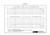
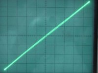
Below one picture shows frequency response and the relative reflected impedance of a good quality steel core transformer (Hashimoto). It's DEAD FLAT from 80-90Hz to 30 KHz, except at the extremes and it is not finished; the other picture is the actual hysteresis loop of steel gapped SE transformer (Tamura) when properly used within its limits.
If one has to use a substantially bigger transformer for the same job it will be more difficult to get the same behaviour at higher frequency because the core is the least of the problems!
Finally, he really needs to use funny probe signals, that have no place in musical signals, to show any difference because with the normal ones a difference cannot be seen. It looks like all the advantages of phase distortions live in the radio frequency range and more of the same useless features.......bla bla bla
As I have always been saying, for years before this thread, these low loss, high permeability cores are useful in PP amps. Physics has not changed, things have not changed.
Attachments
Fochenkov: ".....the operating bias current in the SE takes the operating point from the problematic zero to a very linear section.".....(p.93).
You say: "He (Fochenkov) is forgetting that in proper design SE transformer there is no zero crossing....."
Maybe you understand how fruitless it is to discuss with you when you simply don't read well??
Yes, high permeability cores shine in PP applications, but that does not mean "by definition" that these cores have no merits in SE as well, as Fochenkov points out and our ears tell us.
45 is always rigth and everyone else including Crowhurst is wrong, BW is unimportant, effective capacitance can neither be calculated nor does it appeare at the transformers connections to the tube.
Marek, i wanted to help you applying Yves calculator the best possible way, its a valuable tool if you are aware of its shortcomings, sadly rigth from start, all got sidetracked and buried in noise....
By best ratio i ment highest ratio offcourse, has nothing to do with 20 or 30Hz or whatever but has everything to do for the core type choice IF you have a choice. The core dimension RATIO that can give the highest BW will offer the highest ratio of inductance to leakage, as you sure know, the higher the power the more limited the BW becomes and the more we could gain from knowing this optimum dimension ratios. Thinck about the advantages regarding tube loading, distortion, phaseschift, feedback a.s.o. at the extremes. At the same time, if there is a best ratio to get the highest BW there would also be a worst ratio i would like to know about, so i could get as far away as possible. Just remember, it is not about size, , power or weigth, it is about RATIOS@gorgon53 I did give a answer, I did not wipe anything out but you still do not get it! I regret my decision to answer your questions. You don't have the knowledge, you don't have the experience to understand.
The best possible ratio between inductance and leakage inductance does not exist in practical terms because it does not mean the transformer is optimal. There is a practical, sensible limit as anything else. There is no best ratio of inductance to leakage because it is at expense of something else. At best one can optimize the product of leakage inductance and shunt capacitance but it still depends on the application, power rating and the efficiency. Hence, my answer: the best size is the smallest one can use.
Before optimizing the ratio between inductance and leakage inductance the very first requirement to satisfy is the power rating.
The approximate weight of the core can be estimated based on power rating at low frequency. This one can find from any manufacturer. It is referred to line frequency but it's easy to reformulate for lower frequency.
You will never be able to convince me that 20Hz is the right frequency and 30Hz is a worse compromise because my experience tells me this. The difference in core size between 20Hz and 30Hz is substantial. Core material can change, acceptable losses can change and the shape can change. A C core with a certain cross-section will have a very different winding volume respect to an EI core with same core cross-section. Why all these shapes exist if a toroid could be the only one to do it all? The answer is simple....
The right term is effective capacitance because it is the capacitance one gets once the transformer is in use as intended and the sequence of how internal connections are chosen does make some (useful or nasty) difference. Sorry but you are wrong again.
@gorgon53 What does it mean "If ones has a choice"???? If there were a choice rest assured it would be in the article already. After all that work, are you so naïve to think that Chrowhurst would not know?
The core dimensions ratios in EI transformers, for example, are dictated by manufacturing efficiency. The E's and I's are such that there is minimal waste of material. If you want another core with different dimensions ratio buy a sheet and have it done as you like. I don't think things would change much, it's not worth an effort. You are running after a ghost. C cores have very different ratio but numbers are more or less in the same ballpark. The only thing where they can give some clear advantage is copper loss, if the core size is chosen wisely and with same criteria. But again this is nothing that would change the result like night and day.
The core dimensions ratios in EI transformers, for example, are dictated by manufacturing efficiency. The E's and I's are such that there is minimal waste of material. If you want another core with different dimensions ratio buy a sheet and have it done as you like. I don't think things would change much, it's not worth an effort. You are running after a ghost. C cores have very different ratio but numbers are more or less in the same ballpark. The only thing where they can give some clear advantage is copper loss, if the core size is chosen wisely and with same criteria. But again this is nothing that would change the result like night and day.
Last edited:
I said that there is no zero crossing (we agree) AND there is a minimum DC inductance that is already more than enough. You are not even good at nitpicking....Fochenkov: ".....the operating bias current in the SE takes the operating point from the problematic zero to a very linear section.".....(p.93).
You say: "He (Fochenkov) is forgetting that in proper design SE transformer there is no zero crossing....."
Maybe you understand how fruitless it is to discuss with you when you simply don't read well??
Yes, high permeability cores shine in PP applications, but that does not mean "by definition" that these cores have no merits in SE as well, as Fochenkov points out and our ears tell us.
There can only be a technical discussion on this subject because there is not enough statistics to get some objective result out of subjective opinions. You cannot show or prove anything. You can only declare yourself a believer for now.....
I have not found what you and other people claim about these cores in SE output transformers. It's my opinion and counts as mine only.
Last edited:
Offcourse YOU have no other choice, you are a winder stocking a limited range of lossless stamped EI cores. I am not limited by commercial interrests as you are, I have many more choices than you have, no commercial interest involved in the choices i can make. Anyway, this is going nowhere, as my father once said, there is no point in discussing with somone that has to protect his commercial interrests, he can not afford to admit that there could be better ways to serve his customers best interrest, so, no, i am not naive, i get it...
Last edited:
I have no commercial interest. My final target is always the amplifier. I just don't waste my time with pointless ideas.
No, your idea is pointless. It does not bring anything new to the table, it's more about mirror climbing. That happens when someone thinks he has "brilliant" ideas without having experience and knowledge to assess what he is thinking!
Stop please.
The choise off core dimensions is important.
Not for increasing Ll but for parasistic résistances and capacities.
The ratio stack and lengh
smaller core the better for exemple
Yan
The choise off core dimensions is important.
Not for increasing Ll but for parasistic résistances and capacities.
The ratio stack and lengh
smaller core the better for exemple
Yan
Smaller cores have bigger problems then larger cores, for larger cores things can be solved (bandwidth up to 100kHz is no problem)
Smaller cores problems can not be fixed, in return to get enough low bandwidth the Rdc will be bigger so you introduce another problem.
EI cores: always the worse choice because for every EI is a better c-core available. Not only better linearity but also much lower corelosses, easier to get thinner laminations.
- Home
- Amplifiers
- Tubes / Valves
- Design of C-core nanocrystalline GM-70 output transformer