Clean looking design opc. Congratulations 🙂
Can you please show the THD and THD+N spectral plots at 50Hz, 1kHz and 10kHz? You know a picture speaks a thousand words. I'm want to see how clean the noise floor is.
Also how about IMD plots (60 Hz, 7 kHz)?
Did you think of using the LME49724 diff-amp which is pin compatible with the OPA1632 but has better specs?
Thanks,
David
Hi dmusoke,
Thanks!
All the measurements are coming in the next post, and they will be thorough.
I actually wasn't aware of the LME49724, so thanks for pointing it out! I'm struggling to find a single area in which it's better than the OPA1632 though. It has similar distortion, higher noise, lower slew rate and lower GBP.
If you compare the one THD+N graph that is common between the two datasheets at 3VRMS output then indeed the LME part has lower distortion at high frequencies, but this isn't really a fair comparison because 3VRMS happens to be the lowest possible point for THD for the LME (see figure 13), and isn't for the OPA, which has it's minimum point closer to 5.5VRMS (see figure 3).
I'd say there isn't enough data to conclusively determine which truly has the lower THD+N. It's also worth noting that THD above 8-10kHz really isn't audible since the first harmonic falls outside the range of human hearing. Your dog may object, but you probably won't 🙂
In this application, we are also limited by the DAC itself which contributes a whole lot more distortion than we're talking about with these op-amps 😉
The only advantage I see is that you can run it at +/-18V which could be beneficial in some applications, but not really this one.
Regards,
Owen
Very, very nice.
Are you going to do a run of the boards? I have 3 to redo and a ton of other projects and don't have the time to do a board basically identical to what you've just done.
Not being in NA, I'm probably not the best to organise a GB, but I'd help. I, personally only need PCBs as I have most of the parts including a tube of OPAs.
Alright... moving on to measurements!
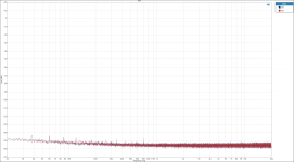
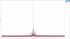
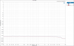
1. Analog Input - Noise Floor
2. Digital Input - Noise Floor
3. Digital Input - THD @ 1kHz
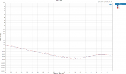
4. Digital Input - THD+N @ 1kHz
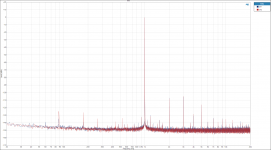
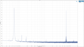
5. Digital Input - FFT 1kHz
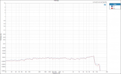
6. Digital Input - THD VS FR -15dBFS
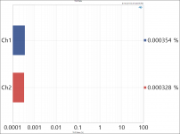
7. Analog Input - THD @ 1kHz
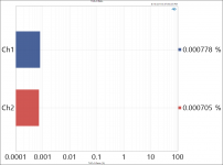
8. Analog Input - THD+N @ 1kHz
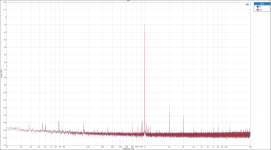
9. Analog Input - FFT 1kHz
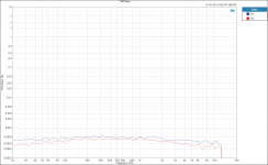
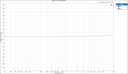
10. Analog Input - THD VS FR 1VRMS
More to come!
1. Analog Input - Noise Floor
2. Digital Input - Noise Floor
3. Digital Input - THD @ 1kHz
4. Digital Input - THD+N @ 1kHz
5. Digital Input - FFT 1kHz
6. Digital Input - THD VS FR -15dBFS
7. Analog Input - THD @ 1kHz
8. Analog Input - THD+N @ 1kHz
9. Analog Input - FFT 1kHz
10. Analog Input - THD VS FR 1VRMS
More to come!
Attachments
-
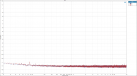 FFT output noise floor analog.png145 KB · Views: 730
 -
 Analog Input THD VS FR 1VRMS.PNG57.8 KB · Views: 206
 -
 Analog Input FFT 1VRMS.PNG157.2 KB · Views: 191
 -
 Analog Input THD+N Ratio 1VRMS.PNG87.1 KB · Views: 165
 -
 Analog Input THD Ratio 1VRMS input.PNG83.2 KB · Views: 185
 -
 THD VS FR -15dBFS.PNG55 KB · Views: 219
 -
 Digital Input FFT 1kHz -15dBFS.PNG158.1 KB · Views: 697
 -
 Digital Input THD+N Ratio 1kHz -10dBFS.PNG84.4 KB · Views: 709
 -
 Digital Input THD Ratio 1kHz -15dBFS.PNG82.3 KB · Views: 707
 -
 FFT output noise floor AES-EBU.png143.6 KB · Views: 707
1. FR and Inter-channel matching with Digital input
2. FR and Inter-channel matching with Analog input
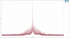
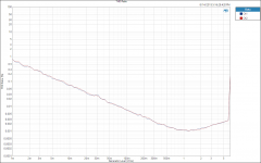
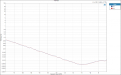
3. Jitter Artifacts - Digital input at 44.1kHz
4. Jitter Artifacts - Digital input at 48kHz
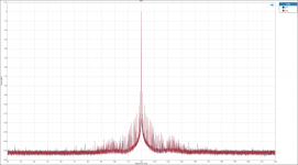
5. Jitter Artifacts - Digital input at 96kHz
6. Jitter Artifacts - Analog input at 96kHz
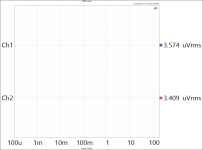
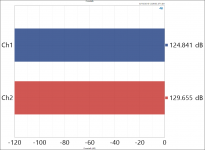
7. Output RMS Level - Digital Input
8. Output RMS Level - Analog Input
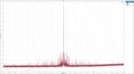
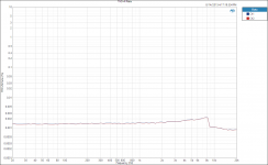
9. FFT 20Hz to 1MHz digital input
10. SNR at 2VRMS
2. FR and Inter-channel matching with Analog input
3. Jitter Artifacts - Digital input at 44.1kHz
4. Jitter Artifacts - Digital input at 48kHz
5. Jitter Artifacts - Digital input at 96kHz
6. Jitter Artifacts - Analog input at 96kHz
7. Output RMS Level - Digital Input
8. Output RMS Level - Analog Input
9. FFT 20Hz to 1MHz digital input
10. SNR at 2VRMS
Attachments
-
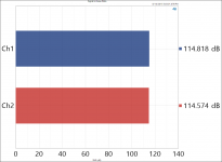 Signal to Noise Ratio 2VRMS.PNG38.1 KB · Views: 161
 -
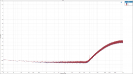 FFT to 1MHz.PNG141.2 KB · Views: 141
 -
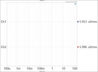 RMS Level Analog.PNG87 KB · Views: 131
 -
 RMS Level AES-EBU.PNG89 KB · Views: 156
 -
 Jitter - 96kHz Analog Input.PNG147.8 KB · Views: 156
 -
 Jitter - 96kHz.PNG175.7 KB · Views: 161
 -
 Jitter - 48kHz.PNG157.3 KB · Views: 170
 -
 Jitter - 44k1Hz.PNG149.4 KB · Views: 165
 -
 Analog Input FR.PNG48.9 KB · Views: 117
 -
 Digital Input FR.PNG48.6 KB · Views: 200
And a few final stragglers...
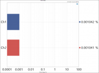
1. Distortion Product Ratio
2. Digital Input THD+N vs. FR
3. Analog Input THD+N vs. FR
4. Digital Input THD vs. Level
5. Analog Input THD vs. Level
6. Crosstalk - adjacent L and R output (out 3 and 4)
7. IMD - SMTPE (60Hz, 7kHz) vs. Level
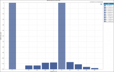
8. IMD - SMTPE (60Hz, 7kHz) FFT
9. IMD - SMTPE Distortion Product Ratio
1. Distortion Product Ratio
2. Digital Input THD+N vs. FR
3. Analog Input THD+N vs. FR
4. Digital Input THD vs. Level
5. Analog Input THD vs. Level
6. Crosstalk - adjacent L and R output (out 3 and 4)
7. IMD - SMTPE (60Hz, 7kHz) vs. Level
8. IMD - SMTPE (60Hz, 7kHz) FFT
9. IMD - SMTPE Distortion Product Ratio
Attachments
-
 FFT - IMD 60Hz 7kHz.png122.9 KB · Views: 139
 -
 SMPTE Ratio.png44.3 KB · Views: 131
 -
 Crosstalk.png41.5 KB · Views: 143
 -
 THD Ratio VS Level Analog Input.PNG61.7 KB · Views: 133
 -
 THD Ratio VS Level - Digital Input.PNG44.6 KB · Views: 132
 -
 Analog Input THD+N VS FR 2VRMS.PNG51.5 KB · Views: 133
 -
 THD+N VS FR -10dBFS.PNG49.7 KB · Views: 145
 -
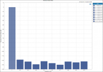 Distortion Product Ratio - Digital Input.png37.9 KB · Views: 171
 -
 SMPTE Distortion Product Ratio.png43.3 KB · Views: 129
Very, very nice.
Are you going to do a run of the boards? I have 3 to redo and a ton of other projects and don't have the time to do a board basically identical to what you've just done.
Not being in NA, I'm probably not the best to organise a GB, but I'd help. I, personally only need PCBs as I have most of the parts including a tube of OPAs.
Hi Brett,
I've got a pile of 38 boards sitting beside me now 😉
If you already have the OPA parts then it's a bit of a no-brainer. Build costs would basically be just the PCB, a few passives and two connectors.
I'll be putting the boards up for sale tomorrow using my usual PCB sign up sheet. They'll be $30 each. I'll add the info to my Wiki page tomorrow as well (schematic and BOM).
Regards,
Owen
Well done opc. The spectral plots are impressive and noise floor is very low indeed. It seems your measurement instrument is the limiting factor here. Is it a PC/MAC-based card system? I have a question on items 7 & 8 "Output RMS Level". Since they are so low, measuring in uV, are they supposed to indicate the output level when the inputs are shorted?
Item 9 looks like the output spectrum of a DSD128 system or is it due to the switching power supply of the measurement system?
Again, your board looks and measures clean. Congratulations!
David
PS
You are right about the similarity between the OPA1630 and LME49724 distortion profiles. I was confusing it with the non diff OPA1612 and the LME49999 where the LME has lower distortion performance.
Last edited:
I'm in for 3 then. I'll PP you as soon as details show.Hi Brett,
I've got a pile of 38 boards sitting beside me now 😉
If you already have the OPA parts then it's a bit of a no-brainer. Build costs would basically be just the PCB, a few passives and two connectors.
I'll be putting the boards up for sale tomorrow using my usual PCB sign up sheet. They'll be $30 each. I'll add the info to my Wiki page tomorrow as well (schematic and BOM).
Regards,
Owen
Hi Mark,
You're always welcome! I'm around for most of the day today, but I do have a few meetings, so we'd need to set up a time.
I've been meaning to bug you about heatsinks as I've used all mine here and need a few more to finish another amp. I think you mentioned you had quite a collection...
Give me a call later today and we can set something up.
Cheers,
Owen
Heats sinks?
I have a few. Actually enough to supply many, many amplifiers.
You want ones with a flat back I'm thinking?
Yes I will give you a call sometime today.
Maybe later in the week we could get together.
I have a few. Actually enough to supply many, many amplifiers.
You want ones with a flat back I'm thinking?
Yes I will give you a call sometime today.
Maybe later in the week we could get together.
I've added myself to the current order form: one phono preamp and one dcx upgrade board. 🙂
Thanks,
Sebastian.
PS: first! 😀
Thanks,
Sebastian.
PS: first! 😀
Awesome!
Thanks sek 🙂
I'll get the BOM and other details posted today on the Wiki.
Regards,
Owen
Thanks sek 🙂
I'll get the BOM and other details posted today on the Wiki.
Regards,
Owen
Hi Guys,
Schematic, BOM, and overall description have been posted to the Wiki here:
The Wire - All Boards and Kits Explained Here! - diyAudio
Please review if you're interested in getting a PCB.
I have also updated the first post of this thread with a link to the order page. The same link can be found on the Wiki.
I will put together a build guide a little later that outlines all the build options, and a few other tips and tricks for a smooth build.
Regards,
Owen
That board would almost certainly fix the jitter issues, and give you a pretty top of the line DAC / Crossover / EQ solution along with the new output board.
I had seen that project before, but my first thought was "nobody is going to want to risk damaging their DCX to install that"
I lifted some of the legs on the receiver IC to test a USB input solution, and in the process damaged two pads on the super cheap PCB in the DCX. It took some precision surgery to get it all working again after that.
If you're brave enough to do it, then you'll have a pretty solid solution on your hands.
If someone wants to buy me one I'll test it 😉
Cheers,
Owen
Last edited:
I see on digikey the LME49724, 296-37390-1-ND is about half the price of the OPA1632D and i guess it will be almost the same measurements with the dac in question. Do you think it is viable as replacement regarding muting?Hi dmusoke,
Thanks!
All the measurements are coming in the next post, and they will be thorough.
I actually wasn't aware of the LME49724, so thanks for pointing it out! I'm struggling to find a single area in which it's better than the OPA1632 though. It has similar distortion, higher noise, lower slew rate and lower GBP.
If you compare the one THD+N graph that is common between the two datasheets at 3VRMS output then indeed the LME part has lower distortion at high frequencies, but this isn't really a fair comparison because 3VRMS happens to be the lowest possible point for THD for the LME (see figure 13), and isn't for the OPA, which has it's minimum point closer to 5.5VRMS (see figure 3).
I'd say there isn't enough data to conclusively determine which truly has the lower THD+N. It's also worth noting that THD above 8-10kHz really isn't audible since the first harmonic falls outside the range of human hearing. Your dog may object, but you probably won't 🙂
In this application, we are also limited by the DAC itself which contributes a whole lot more distortion than we're talking about with these op-amps 😉
The only advantage I see is that you can run it at +/-18V which could be beneficial in some applications, but not really this one.
Regards,
Owen
I have used parallelled DCXes for ten years to play really loud at short distance. (7 way system with distributed basses under my roomboundary freqyency, 70 Hz. But the stand by noise, when the music is off, is a little anoying. Then i treasure the poppless on/off.
And DCX is not tireing for me if played loud with dynamic music, but the music feels real:
http://www.tcelectronic.com/media/2040040/mobile-test-paper-2013.pdf
Regards Torgeir
https://sites.google.com/site/passivefilter/
Hi Torgeir,
Indeed, the performance of the LME part should be identical in this particular application, so if it's lower cost, then certainly would be worth using.
The mute implementation will work with both op-amps, so that side should be fine too.
For the prices I'm seeing on Mouser / DK it's about a $25 savings per board which is very significant. I'd say go for it!
Regards,
Owen
Not sure what package that IC is, but McMaster-Carr sells a grinding bit with a diameter of 0.060" that would fit in a Dremel. Cutting the pin in between the die and the pad might be an option.That board would almost certainly fix the jitter issues, and give you a pretty top of the line DAC / Crossover / EQ solution along with the new output board.
I had seen that project before, but my first thought was "nobody is going to want to risk damaging their DCX to install that"
I lifted some of the legs on the receiver IC to test a USB input solution, and in the process damaged two pads on the super cheap PCB in the DCX. It took some precision surgery to get it all working again after that.
If you're brave enough to do it, then you'll have a pretty solid solution on your hands.
If someone wants to buy me one I'll test it 😉
Cheers,
Owen
Last edited:
- Status
- Not open for further replies.
- Home
- Source & Line
- Digital Line Level
- DCX2496 Upgrade Board - Objectively Tackling the Improvement of a Stock DCX2496