in my application, I need the maximum number of inputs, so I will be using the DCX2496 effectively as a 3 channel processor with 3 ins and 3 outputs, routed 1 to 1. Adding the DEQ gives me a total of 8 inputs I need to cover. (I am still operating on the assumption that whatever I do for the ins and outs of the DCX will apply equally to the ins and outs of the DEQ)
I am no stranger to making customized PC boards and working with (relatively large, nothing too too small) SMT. However, I am a builder, not a designer when it comes to electronics. Is there a relatively straightforward schematic floating out there that I can follow that even specifies the parts well enough that I can create an order list of components? I can take it from there to make the board, route the signal, etc. But I so far have not been able to find a particularly well-spoonfed schematic for an input circuit yet.
Does anyone here have one they can share that I can just copy x8 then integrate?
Look for Jan Didden's modifications. He designed new input circuits and boards which also add in remote control functionality. It's a really first-rate design.
I found his page, but no schematic. I now found Gary Pimm's schematic which seems easy enough, BUT
I'm not sure I want to go to transformers, and his design requires modifying the DCX board itself which I would like to avoid. Is there a circuit that is reasonably close to the one above that perhaps eliminates the need for transformers?
-----------
I could just copy the input board schematic and just replace the opamp with the OPA4134's and delete the mic input section of inC, but now I'm in guess-and-pray territory (not a designer) and there are ALOT of components, and I don't know which others to change (ie film caps... where?)
Surely there is a happy medium for boneheads with soldering irons?
An externally hosted image should be here but it was not working when we last tested it.
I'm not sure I want to go to transformers, and his design requires modifying the DCX board itself which I would like to avoid. Is there a circuit that is reasonably close to the one above that perhaps eliminates the need for transformers?
-----------
I could just copy the input board schematic and just replace the opamp with the OPA4134's and delete the mic input section of inC, but now I'm in guess-and-pray territory (not a designer) and there are ALOT of components, and I don't know which others to change (ie film caps... where?)
Surely there is a happy medium for boneheads with soldering irons?
Last edited:
Hi whiterabbit,
I'm not sure why you would need 8 transformers when the DCX and DEQ each only have 2 analog inputs.
Regardless though, I would avoid transformers as they are indeed expensive and don't bring anything to the table in this case.
For the input, the ADC needs each phase to be biased at half the analog supply voltage for the ADC. In this case, that's 2.5VDC.
The easiest way to accomplish this is to use a differential ADC driver like the OPA1632 and feed it's VCOM pin with a buffered 2.5V derived from the ADC analog supply through a precision resistor divider.
IIRC the input voltage on the ADC needs to be ~1.7VRMS for 0dBFS, so you need to adjust your gain according to whatever voltage you plan to feed the ADC.
If you really need to be passive, you might get away with a pair of decoupling caps, and two resistors after the caps connected to the derived 2.5VDC to bias the inputs to the ADC. I've never tried this, but it could work. It's likely you would still need a buffer for the VCOM voltage.
Regards,
Owen
Hi Owen,
I'm looking at this much more carefully now. I have the datasheet open
http://www.ti.com/lit/ds/symlink/opa1632.pdf
With an example circuit that is much simplified. So if I understand correctly your recommendation:
-OPA1632 gets powered by +/- 15V from PSU2496.
-delete opamp from datasheet circuit and replace with voltage divider network via 1% resistors to feed Vcom 2.5V (divide what? +15 and Agnd?)
-Use film caps for C1, 2, 3. The others can be 'inexpensive'
-PCM1804 is not used. The lines there directly feed the DCX board.
- buffer for Vcom..... help? (wait, is the buffer the opamp?)
-enable pin, disconnect. Internally pulled up.
-Copy x8 and feed the A, B, C in's of 2x DCX and ins of DEQ.
Do I have it right?
Hi whiterabbit,
Glad you're looking into it! See attached a schematic for an input/output board I made for the Behringer DCX.
Everything you need is there, and I've built/measured this so I can attest to it working very well.
I omitted input and output low pass filters and I'm perfectly happy without them. You can always add them in if desired.
Regards,
Owen
Attachments
wow, that is really handy, thank you! I'm trying to digest the schematic and have just a couple questions:
1. for the non polar capacitors, do I need to worry about special capacitors? Can I just pick an available plastic film cap or mica cap?. I assume I can pick up any available 1% resistors?
2. I am unclear on the purpose of the ADM7150. What is it doing for the circuit? J7? Do I need this?
3. Q1, can I use any standard body diode mosfet? Fairchild 2N7002?
-----
I can delete the XLR for the digital input and add a third input circuit for inC without worrying about overloading the TPS IC's. Is this a true statement?
-----
Oh golly, now I see the TPS7A4700 IC is a QFN package (the other TPS available in TO-220-7). I'm not sure I can solder a QFN. Is there an alternative package? I hate to ask since there is obviously going to be a reason for it, but why not just drive the OPA's using +/- 15V from the ribbon cable directly?
Last edited:
White,
opc uses the same symbol for all the "grounds" in that pdf.
Note that the ground symbol for the in/out sockets is NOT audio ground.
Pin1 of every in/out socket goes to Chassis right next to the socket with the shortest, widest, multi-strand cable you can insert there.
If you can electrically connect the socket to the chassis all the way around the socket/chassis hole, then you improve the RF coupling of the socket shell to the chassis. This then acts as a screen around the pins in the XLR.
opc,
what do the chips tps do?
TPS7A4700, TPS7A3301 and ADM7150 are low noise regulator ICs.
OPC, are you willing to field a couple dumb questions (since I am no EE)? It would very much help me.
I am about ready to move forward with my board. It will be a tester for a DEQ (so I only put together 4x channels rather than the full 9 for the DCX). I modified the circuit slightly. Two changes:
1. I removed the 12V regulators. I assume they are there to get that last bit of hiigh fidelity performance from the analog stage, but my environment is such that I could not take advantage. For me, a very low noise floor with no change in OEM gain would be the only need, any gain in fidelity over the OEM analog stage is bonus after that. Combine that with a not-insignificant cost and difficult package to deal with and it is an advantage to remove the extra regulation. Can I assume this is OK, and the only "cost" to my sound is (an expected very-minor) loss in fidelity? Is that a true statement?
2. This is where I really need a second opinion. I used someone else's 2.5v circuit due to requiring fewer components. It uses an LM285 with a couple resistors and a filter cap. I chose this because without the tightly regulated 12V circuit, using voltage dividers was not as confidence-inspiring for generating 2.5v. Are there any sonic costs I should be aware of going this route?
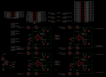
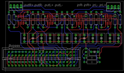
I uploaded screen caps of my schematic and planned board. The whole thing will sit on top of the DEQ, allowing me to use a much smaller chassis.
I am about ready to move forward with my board. It will be a tester for a DEQ (so I only put together 4x channels rather than the full 9 for the DCX). I modified the circuit slightly. Two changes:
1. I removed the 12V regulators. I assume they are there to get that last bit of hiigh fidelity performance from the analog stage, but my environment is such that I could not take advantage. For me, a very low noise floor with no change in OEM gain would be the only need, any gain in fidelity over the OEM analog stage is bonus after that. Combine that with a not-insignificant cost and difficult package to deal with and it is an advantage to remove the extra regulation. Can I assume this is OK, and the only "cost" to my sound is (an expected very-minor) loss in fidelity? Is that a true statement?
2. This is where I really need a second opinion. I used someone else's 2.5v circuit due to requiring fewer components. It uses an LM285 with a couple resistors and a filter cap. I chose this because without the tightly regulated 12V circuit, using voltage dividers was not as confidence-inspiring for generating 2.5v. Are there any sonic costs I should be aware of going this route?
I uploaded screen caps of my schematic and planned board. The whole thing will sit on top of the DEQ, allowing me to use a much smaller chassis.
Attachments

1. I removed the 12V regulators. I assume they are there to get that last bit of hiigh fidelity performance from the analog stage, but my environment is such that I could not take advantage. For me, a very low noise floor with no change in OEM gain would be the only need, any gain in fidelity over the OEM analog stage is bonus after that. Combine that with a not-insignificant cost and difficult package to deal with and it is an advantage to remove the extra regulation. Can I assume this is OK, and the only "cost" to my sound is (an expected very-minor) loss in fidelity? Is that a true statement?
It's perfectly fine to omit the 12V regulators from the design. They may provide an ever-so-slightly better noise floor, but it's probably not worth the added cost and complexity. Just power everything off the existing +/- 15V rails in either the DCX or DEQ.
2. This is where I really need a second opinion. I used someone else's 2.5v circuit due to requiring fewer components. It uses an LM285 with a couple resistors and a filter cap. I chose this because without the tightly regulated 12V circuit, using voltage dividers was not as confidence-inspiring for generating 2.5v. Are there any sonic costs I should be aware of going this route?
This is one area you really should be careful. This voltage is critical as it's the reference voltage for the ADC inputs, which means the audio signal will be referenced to this voltage. Any noise or fluctuation here will have a significant impact on the performance of the ADC. It's always best to derive it directly from the 5V analog supply for the ADC (which is readily available) and use a high precision resistor divider with a buffer to drive the VCOM pin on the OPA1632. This way, it tracks the ADC supply voltage, which has several advantages. This voltage is critical enough that it's worth the added trouble and expense.
Regards,
Owen
Hi Owen,
One last question. The DCX has a "5V" and a "5VA1", looks to me like the DCX derived its own 5V just for hte analog side. So that made perfect sense.
The DEQ as far as I can tell does not do this? I just have access to "5V" from the power supply on the 40 pin connector. I'm not sure I can guarantee this voltage will be 5.00 volts, and assumed it was used for "digital stuff" besides. Can I use the 5v if it is designated 5v, and not 5vA1? If so I can modify the circuit right away to use your suggested design, digikey of course has all the parts.
I'm just not confident I can use "any old 5v" found with respect to the DEQ. So, do you think it would be better for me to use tight-tolerance resistors on the standard 5v to divide to 2.5 and go through a buffer, or for the deq, will the LM285 be the better choice?
(I will definitely use your circuit for the DCX's when I get there since I have the 5vA1 pin to work with)
Hi owen,
I can't delete the above post. You can disregard it. I have to pipe over analog 5V from the main board, I don't think it's on the 40 pin connector. But it can be done. Quick jumper wire and it's good to go.
And it's even just simple through hole soldering.
I can't delete the above post. You can disregard it. I have to pipe over analog 5V from the main board, I don't think it's on the 40 pin connector. But it can be done. Quick jumper wire and it's good to go.
And it's even just simple through hole soldering.
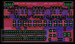
Final board, thanks Owen.
It's huge @ 2"x3.5", but the traces are so far apart and all through hole components minus five SOIC's that even a fool (me) can put it together. Including using the toner transfer method to just make a board at home, since we're talking about a one-off. Might use a build house for a DCX version and order 3x.
Looks like $70 at digikey buys all the components to do one DEQ and two DCX minus the $6 opa1632's for the DCX processors. (and the boards of course).
Steve
Attachments
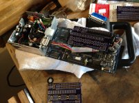
I changed the connectors a bit, but other than that, I build one board. I forgot how tough it is to align connectors when there are more than 3 pins (much less 40!) so I sent it off to a build house to make for me. I hope the performance works out without having to dig into the analog 5v supply, clock, etc. For me, if I can get the whole DEQ package into a chassis that is the same footprint as the DSP+PSU side-by-side with equivalent or better sonic performance and equivalent or better noise floor I am golden.
Will put in the digikey order late this week for the parts.
Huge thanks.
Will put in the digikey order late this week for the parts.
Huge thanks.
Hi Owen,
I built the board the other day. Minus some small hiccups, it works! clear sound, no noise floor (or at least, no change in noise performance compared to the original on the test bench).
Success!
(minus some odd decisions I wish I did not make, like lining all the caps up together)
Anyways, I am posting because I want to ask you, what is the danger of replacing the 1.18k ohm resistors with 1.5k? Or replacing the 1k resistors with 800 ohm resistors? Should give me about 30% more gain?
Attachments
I've ordered one of these units to tinker with, but it seems like most of the documentation and pages with instructions and pinouts are half dead, or no longer being offered.
I'm interested in the simplest form of passive outputs, as it seems most of the mods that relate to input mods ditch one of the inputs, which I need for 3 in 6 out.
Does anyone have a link that still works or a copy of the instructions from here: passive output stage for Behringer DCX2496 ? I have all the parts necessary to complete the single ended version of this mod, however most of the pages in the middle of the article that get into ribbon cables and pinouts are dead.
Halp!
- Status
- Not open for further replies.
- Home
- Source & Line
- Digital Line Level
- DCX2496 Upgrade Board - Objectively Tackling the Improvement of a Stock DCX2496