That passive output solution was discussed on this Forum.
Another very similar was also tried.
Both appeared to work.
You can maintain a passive balanced output if you assemble two outputs for each channel.
Another very similar was also tried.
Both appeared to work.
You can maintain a passive balanced output if you assemble two outputs for each channel.
I think the AX article on this is posted on Jan Didden's website.
I read through that one, and pretty much every link I can still find now in 2015 that hasn't been dead since 2008 😛
The AX article is great and all, but I'm not sure that I'm looking to build a complete replacement output board, unless someone still has some blank boards sitting around, or better yet, has a modded DCX they no longer use and would be interested in trading it for a NIB unit.
I have the caps and resistors, along with a breadboard to use for the plain jane single ended output mod, the only problem is, the one good page I can find with a project I can copy has pages 1 through 5, but page 6 and on (the pages with pinouts and pictures of the project actually wired, with breadboard placed) are dead links that just refer back to the root page.
I also can not lose that third input. This seems to be a popular omitted part, as I guess most people only use and acknowledge 2 input channels...unless I've completely misunderstood this unit and will have to return it anyway, so I can't completely remove the rear board.
I'm starting to think maybe this unit is too old, and I was too hasty to order one, searching for info on these mods seems a bit like searching for windows 95 information.
The article I have in mind is just the passive outputs. That was easy, took less than an afternoon to do, and it made a real improvement.
Changing the output board does nothing to the preceding stages.
You still have 3 inputs.
Ah, I was under the impression that the output, input and RS232 connection were all on the same PCB, so I can't yank it unless I also mod the inputs and rewire the serial cable.
I guess I'll vacuum the XLR connectors and order some Neutrik RCA jacks to go into the holes so I don't have to pull the board, if anyone's done that and can attest that it'd fit like that.
And all the while, the sneaking suspicion that there's a protea 3.6 sitting on a shelf somewhere laughing at me....or better yet, I'll get finished and the Venu 360 release will be announced 😱
you can't. The passive output mod requires that you keep the IO board for the inputs and RS232. folks that ditch the I board but ONLY passive output mod it are likely using the digital input only.
I noticed the same thing. Try "the way back machine". it helped me find some DCX resources that are now gone.
You are lucky. there are a TON of resources out there for the DCX that simply do not exist for the DEQ. I would sorely love to have the microphone input circuit for the DEQ, and it's just not going to happen. But that's small fry compared to the ins and outs, and that at least is documented.
I would sorely love to have the microphone input circuit for the DEQ, and it's just not going to happen. But that's small fry compared to the ins and outs, and that at least is documented.
Part of my issue with the replacement I/O board is it seems that a lot of them are assembled assuming that input C is only used for the microphone / delay calculator, I'm actually needing to use it for a 3rd analog input. I need 3x 2 way crossovers, which is why I think I can't use the complete replacement board, even with the additional board for the C input.
It seems from the reading I'm able to do, the C input addon board is fitted with a microphone preamp only
 , abandoning the capability to use it as a line level analog input, unless I've read everything wrong, and am going to have to return the unit anyway. :S
I don't understand.
DrDyna, I'm doing the exact same thing you want to do. The input C is just another analog input, identical to A and B. You have to specifically enable relmic to make it a mic input (to run through the mic circuit). You just leave that alone. Just duplicate whatever input circuit you are using (for passive people say use a transformer with a 2.5 volt bias on thte something or other, I don't know, transformers are expensive and Owen attached a WONDERFUL schematic here that uses opamps. That's what I am using.)
anyways. Whatever you do for inA and inB, just do it for inC. Leave Relmic alone. You are done.
Last edited:
I don't understand.
DrDyna, I'm doing the exact same thing you want to do. The input C is just another analog input, identical to A and B. You have to specifically enable relmic to make it a mic input (to run through the mic circuit). You just leave that alone. Just duplicate whatever input circuit you are using (for passive people say use a transformer with a 2.5 volt bias on thte something or other, I don't know, transformers are expensive and Owen attached a WONDERFUL schematic here that uses opamps. That's what I am using.)
anyways. Whatever you do for inA and inB, just do it for inC. Leave Relmic alone. You are done.
Right, I'm just miffing a bit about the replacement I/O boards. My mod will be done with a breadboard and stuffed in there. I just wish there was a version of one of the replacement I/O boards where I read the page describing it and it's not "Welp, here's your A and B inputs, we're going to leave out the microphone (actually 3rd input) input because reasons."
Edit: Because Id rather just have a nice, clean i/o board like some of the ones posted, but can't....unless there's a 3x6 replacement board or kit that I just missed, or is lost in the sea of 404 errors most of these projects seem to have ><
Last edited:
I bought an SRP4004/27 remote control, and have tried programming it for Loewe and Loewe-opta, as they are implementations of the RC5 protocol.
Now, the thing is that Philips says you cannot program the remote without having a TV around to turn on/off with the remote.
Is this true? If so, then how can I get a remote control to work?
Thanks.
Not sure what this has to do with the DCX2496.
Did you post this in the wrong thread by mistake?
Regards,
Owen
Please send Jan an email or a PM, or open up a new thread if you feel the question and answer are of value to the community at large.
This thread does not pertain to Jan's board, so asking here is spamming everyone currently subscribed to this thread with a question that is not relevant to the thread.
Regards,
Owen
This thread does not pertain to Jan's board, so asking here is spamming everyone currently subscribed to this thread with a question that is not relevant to the thread.
Regards,
Owen
Just been ghosting about this website for the few days and would like to thank you Owen for the heart you have to freely give and educate the masses out there about your diy designs. Very informative and refreshing indeed. Myself being an EE (with an MS degree), I was surprised at the cost and simplicity of the circuits you presented and wondering why the commercial market charges $$$$ for something that should cost a few hundred dollars.
Please keep up the good work. Now how does one get hold of an affordable AP Test system...
David
Please keep up the good work. Now how does one get hold of an affordable AP Test system...
David
Just been ghosting about this website for the few days and would like to thank you Owen for the heart you have to freely give and educate the masses out there about your diy designs. Very informative and refreshing indeed. Myself being an EE (with an MS degree), I was surprised at the cost and simplicity of the circuits you presented and wondering why the commercial market charges $$$$ for something that should cost a few hundred dollars.
Thanks for the kind words! I've learned an awful lot from this website over the years, and I still don't know if I've given back as much as I've got.
Now how does one get hold of an affordable AP Test system...
Unfortunately, you can't... and I've certainly tried!
I'm lucky enough to have access to an APx585 through work, but I've looked into getting one myself and there isn't really an affordable option. The APx515 is as cheap as they get, and you're still looking at over $10k with options.
The latest APx555 is well over $30k with options, and that's the one I'd really want 🙂
One of my more ambitious ongoing projects is a PC based measurement system that could use something like Spectra Plus (or any other good spectrum analyzer SW) with a really good hardware front end based on an XMOS USB sound card IC and an ESS DAC and ADC to achieve similar performance to an APx525 for less than $1000.
The sticking point with that is managing the input side of things, which is actually very challenging. Auto scaling to accept inputs from less than 1mV up to a few hundred volts while maintaining low noise and distortion and protecting the input of the ADC is not trivial.
Still, I feel that having something like that within the reach of the average hobbyist would make for a huge step towards proper objective design and evaluation. I know it helped change the way I look at audio, and it would be good to allow others to have the same experience!
Cheers,
Owen
I like where you are going with the design of an affordable audio test system as I have been thinking about the same thing for a while now. The challenges you present about the front end design are real and indeed not trivial. I would pare down the maximum input voltage from hundreds to about 30Vrms. I believe the current AP system takes in about 26 - 27vrms maximum(but I may be wrong here). Once you solve the huge dynamic range requirements of the front end, then the rest is software and PC speed which is plentiful. I know....easier said than done 🙂
I like where you are going with the design of an affordable audio test system as I have been thinking about the same thing for a while now. The challenges you present about the front end design are real and indeed not trivial. I would pare down the maximum input voltage from hundreds to about 30Vrms. I believe the current AP system takes in about 26 - 27vrms maximum(but I may be wrong here). Once you solve the huge dynamic range requirements of the front end, then the rest is software and PC speed which is plentiful. I know....easier said than done 🙂
May look here and ask for news...😀
http://www.diyaudio.com/forums/equipment-tools/245852-buffers-adc-design-ak5394a-other-adcs.html
Hp
Hi Guys,
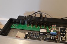
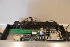
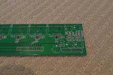
It has been a long while since I’ve posted on this thread, but I finally went ahead and designed/built an output board for the DCX.
It’s not going to fix the jitter issues inherent to the ASRC, but it will bring the output stage and overall analog performance from “Poor” to “Very Good”, all while improving overall functionality.
Here’s what I did in a nutshell:
1. Replaced all the output stages with a single OPA1632 differential op-amp per output.
2. Set output gain to be 2VRMS at 0dBFS to reduce noise and excessive output levels.
3. Maintained mute functionality to reduce start-up and shut-down clicks and pops
4. Replaced the two main input stages with a single OPA1632 differential op-amp to drive the analog inputs to the ADC.
5. Fully DC coupled inputs and outputs. No caps in the signal path. No DC offset.
6. Provided two ultra-low noise regulators on board to further filter the supplies for the op-amps. These can be bypassed if desired.
7. Provided an ultra-low noise voltage reference for the analog inputs to the ADC using an LME49990 opamp.
8. Replaced the third analog input with a dedicated AES/EBU digital input and eliminated the MIC input circuit and relay. No more switching cables!
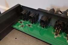
9. Drop-in replacement that doesn’t require any chassis modification.
10. Removed support for RS232 and LINK Ethernet connections.
11. Shortened and direct routed power and output ribbon cables for lower noise.
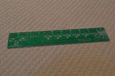
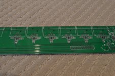
The PCB itself is a 2-layer design that spans the entire back of the unit. It has a full ground plane on the bottom, and the signal traces and ground plane on the top.
Overall, the performance with the new output board is excellent. I ran a full set of measurements to compare to those made on the first page of this thread, and overall, the noise floor is down about 25dB with a complete elimination of all the hash that dominated the output when running the digital input. With the old board, there were a number of correlated noise spikes that regularly hit -95dBV and with the new board the highest correlated noise spike is down at -135dB.
For the digital inputs, the THD has been reduced from about 0.0033% to 0.00034% and THD+N has been reduced from about 0.004% to about 0.00075%. For the analog inputs, the THD has been reduced from about 0.004% to 0.00077% and THD+N has been reduced from about 0.0044% to about 0.001%.
The whole PCB can be built for less than $100, or significantly less than $100 if someone organized a group buy for the parts.
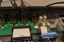
See attached a few pictures of the board and the board installed in my DCX. All add some follow-up posts with measurements and some more details.
Regards,
Owen
It has been a long while since I’ve posted on this thread, but I finally went ahead and designed/built an output board for the DCX.
It’s not going to fix the jitter issues inherent to the ASRC, but it will bring the output stage and overall analog performance from “Poor” to “Very Good”, all while improving overall functionality.
Here’s what I did in a nutshell:
1. Replaced all the output stages with a single OPA1632 differential op-amp per output.
2. Set output gain to be 2VRMS at 0dBFS to reduce noise and excessive output levels.
3. Maintained mute functionality to reduce start-up and shut-down clicks and pops
4. Replaced the two main input stages with a single OPA1632 differential op-amp to drive the analog inputs to the ADC.
5. Fully DC coupled inputs and outputs. No caps in the signal path. No DC offset.
6. Provided two ultra-low noise regulators on board to further filter the supplies for the op-amps. These can be bypassed if desired.
7. Provided an ultra-low noise voltage reference for the analog inputs to the ADC using an LME49990 opamp.
8. Replaced the third analog input with a dedicated AES/EBU digital input and eliminated the MIC input circuit and relay. No more switching cables!
9. Drop-in replacement that doesn’t require any chassis modification.
10. Removed support for RS232 and LINK Ethernet connections.
11. Shortened and direct routed power and output ribbon cables for lower noise.
The PCB itself is a 2-layer design that spans the entire back of the unit. It has a full ground plane on the bottom, and the signal traces and ground plane on the top.
Overall, the performance with the new output board is excellent. I ran a full set of measurements to compare to those made on the first page of this thread, and overall, the noise floor is down about 25dB with a complete elimination of all the hash that dominated the output when running the digital input. With the old board, there were a number of correlated noise spikes that regularly hit -95dBV and with the new board the highest correlated noise spike is down at -135dB.
For the digital inputs, the THD has been reduced from about 0.0033% to 0.00034% and THD+N has been reduced from about 0.004% to about 0.00075%. For the analog inputs, the THD has been reduced from about 0.004% to 0.00077% and THD+N has been reduced from about 0.0044% to about 0.001%.
The whole PCB can be built for less than $100, or significantly less than $100 if someone organized a group buy for the parts.
See attached a few pictures of the board and the board installed in my DCX. All add some follow-up posts with measurements and some more details.
Regards,
Owen
Attachments
-
 DSC_0141.JPG113.6 KB · Views: 958
 -
 DSC_0142.JPG103.7 KB · Views: 849
 -
 DSC_0123.JPG133.1 KB · Views: 826
 -
 DSC_0124.JPG125.2 KB · Views: 827
 -
 DSC_0125.JPG126.9 KB · Views: 820
 -
 DSC_0127.JPG132.3 KB · Views: 312
 -
 DSC_0132.JPG119.3 KB · Views: 334
 -
 DSC_0137.JPG130.7 KB · Views: 387
 -
 DSC_0138.JPG117.7 KB · Views: 425
- Status
- Not open for further replies.
- Home
- Source & Line
- Digital Line Level
- DCX2496 Upgrade Board - Objectively Tackling the Improvement of a Stock DCX2496