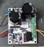
FX100 PSU with flat bridge rectifier.
Built it.
Attachments
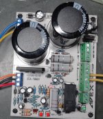
Built it.
Very nice... Just confirm that two 5w res are 0.1ohm
Reg
Prasi
Hello Terry
greetings really fast work in picture you use 560 ohms in parallel with the 2
in4148 in series any reason schematic shows 1K on my protype build over
current protection would kick in at 70% volume on 2 pair ax14 version adding
.22 5 watt in parallel with the existing .1 solved the problems
warm regards
Andrew
In addition to above the 4148 diode appears to be reversed.Hello Terry
greetings really fast work in picture you use 560 ohms in parallel with the 2
in4148 in series any reason schematic shows 1K on my protype build over
current protection would kick in at 70% volume on 2 pair ax14 version adding
.22 5 watt in parallel with the existing .1 solved the problems
warm regards
Andrew
Need some advice for the FX100 amp as per post #540. C9 and C10 are 10pF as per sch. But I have either 4.7p or 22p in stock. I have right now soldered 22p 50V in those places. I also have 24p 100V. Which one should I use?
reg
prasi
reg
prasi
Need some advice for the FX100 amp as per post #540. C9 and C10 are 10pF as per sch. But I have either 4.7p or 22p in stock. I have right now soldered 22p 50V in those places. I also have 24p 100V. Which one should I use?
reg
prasi
Use 24p 100V
Regards
FX100 PSU pdf and sprint files.
Hi Sonal,
Do you have a schematic that matches your layout? Mine is not working and I'm having trouble finding the error without the schematic.
Thanks, Terry
Use 24p 100V
Regards
two 22p in series = 11pFNeed some advice for the FX100 amp as per post #540. C9 and C10 are 10pF as per sch. But I have either 4.7p or 22p in stock. I have right now soldered 22p 50V in those places. I also have 24p 100V. Which one should I use?
reg
prasi
two 4p7F in parallel = 9p4F
Hi Sonal,
Do you have a schematic that matches your layout? Mine is not working and I'm having trouble finding the error without the schematic.
Thanks, Terry
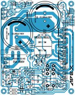
Layout is ok but Polarity of 10uF/ 100V capacitor near 1k2 5W resistor is reversed. I missed it on revision of layout. I have attached corrected photo.
Attachments
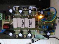
And we have very good news! the amp plays really nice. I have installed all 3 pairs and playing music thro test speakers.
I figured the problem with hum was due to me twisting both left and right channel grounds together on the i/p.
Also, it seems the amp gets better and better with bias with 3 pairs. earlier it was around 70-72 mA per pair with 32 V supply- not so good. Now its 90mA per pair with 45V supply, really nice. I would like to increase it further to try but current heatsink is limiting factor.
Thank you Mr. Mile!.
@ Andrew
Ah! why didnt I think of that!. Guess when I am building something, I miss even trivial calculations. Thanks for the tip, but its working fine with 24p in those places.😀
reg
Prasi
sorry for poor quality pic, its mid night here and too lazy to get the camera out.
Attachments
schematic?
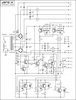
Schematic for FX100PSU, from what I understand 10uF/100V capacitor in reverse polarity is causing short-circuit of BC546 base to ground.
Attachments
Hi Sonal,
Yes, with the cap reversed the relay now engages, however I have 29VDC across the relay, should be ~24VDC.
I have the schematic you just posted but it does not match your layout.
Yes, with the cap reversed the relay now engages, however I have 29VDC across the relay, should be ~24VDC.
I have the schematic you just posted but it does not match your layout.
And we have very good news! the amp plays really nice. I have installed all 3 pairs and playing music thro test speakers.
I figured the problem with hum was due to me twisting both left and right channel grounds together on the i/p.
Also, it seems the amp gets better and better with bias with 3 pairs. earlier it was around 70-72 mA per pair with 32 V supply- not so good. Now its 90mA per pair with 45V supply, really nice. I would like to increase it further to try but current heatsink is limiting factor.
Thank you Mr. Mile!.
@ Andrew
Ah! why didnt I think of that!. Guess when I am building something, I miss even trivial calculations. Thanks for the tip, but its working fine with 24p in those places.😀
reg
Prasi
sorry for poor quality pic, its mid night here and too lazy to get the camera out.
Nice work.
Regards
Hi Sonal,
Yes, with the cap reversed the relay now engages, however I have 29VDC across the relay, should be ~24VDC.
I have the schematic you just posted but it does not match your layout.
29VDC is ok for 24V relay.
- Home
- Amplifiers
- Solid State
- DC Servo MOSFET Amplifier