I still have the Sprint file with suggestion by mister Mile post #436 completed later I will show you guys how it look 🙂
this is unusually high unless there is a severely unbalanced load on the two supply rails. I typically see 0Vdc to 0.2Vdc difference in supply rails from my transformers. I think you need to investigate further.This is too slow.
one or two seconds to trip for <2Vdc offset is usual for a competent offset detector. 4 to 5V of offset should give near instantaneous tripping, maybe <<0.5seconds.
10V offset should sound instantaneous.
This detector should NOT trip with a continuous 20Hz @ maximum sinewave at it's input.
I am not saying what it should or shouldn't do. I am reporting what it does do. My only explanation for the difference in voltages is that the positive rail passes through two 1R resistors but the negative rail doesn't. It is direct. These tests were performed with no load attached so that may change once I hook up the amp to it. I was a little surprised that it took so long to trip. I initially tested the DC trip function using the 15v from the little auxiliary circuit. It takes maybe 1/2 a second to trip. Then I used a little DC power supply that I have that produces 1.5v increments starting at 3v. As I said, 3v won't trip it but 4.5v will but it takes 2-3 seconds. With each jump in voltage it reacts a little quicker. I'm not sure how the short circuit protection is supposed to work but I tried shorting the speaker in and the speaker out Jacks and none of them would cause it to trip.
Last edited:
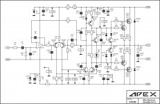
I just looked again and I have 1R/5W installed and it calls for 0R1/5W. I will change those and remeasure. That does pose the question as to what the purpose is for those resistors and why they are only on the positive rail.
I just looked again and I have 1R/5W installed and it calls for 0R1/5W. I will change those and remeasure. That does pose the question as to what the purpose is for those resistors and why they are only on the positive rail.
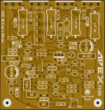
Terry can you show the image of where the "1R 5W" is located I'm confuse 😕
Regards
Juan
Terry can you show the image of where the "1R 5W" is located I'm confuse 😕
Regards
Juan
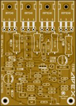
See attached.
I just replaced the 1R with 0R1 and see no change. I read +64.4vdc/-64.9vdc. I even tried reversing the AC leads from the transformer with no change.
Attachments
See attached.
I just replaced the 1R with 0R1 and see no change. I read +64.4vdc/-64.9vdc. I even tried reversing the AC leads from the transformer with no change.
Check those 2N5401 maybe one of them are no as matched as the other one " I think that might be the reason"
this probably change after load is apply with the F100's so the difference is just -0.5V on the negative rail
Attachments
Check those 2N5401 maybe one of them are no as matched as the other one " I think that might be the reason"
this probably change after load is apply with the F100's so the difference is just -0.5V on the negative rail
Both + rails read the same so I doubt it is the 2N5401. It is probably because the + rail had that additional circuitry connected and the - rail just goes directly out. I doubt the amp will care about a 1/2v difference, I just wanted to report my findings.
The sight difference in +Vsup and -Vsup is ok, and is expected with this supply when loaded, the 0.1R resistors look like the current sensing resistors. The project only monitor the positive trails for over current protection.
Terry are you using same pcb as post 466
This circuit should trip when to much current is drawn from + supply rail. If not drawing current it won't trip
Terry are you using same pcb as post 466
This circuit should trip when to much current is drawn from + supply rail. If not drawing current it won't trip
Last edited:
you right, have you hook up the F100 yet ? 🙂
I have now. The PSU works better with the load attached. . +60.1/-60.3. The amp doesn't notice it at all. Only 2mv offset on the speaker out. I haven't tried playing music through it yet.
More later
I have now. The PSU works better with the load attached. . +60.1/-60.3. The amp doesn't notice it at all. Only 2mv offset on the speaker out. I haven't tried playing music through it yet.
More later
that is awesome Terry ! 🙂 I'm glad the layout works well let me know how is the music sound come out from F100, it most sound lovely I bet
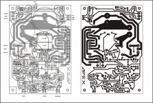
I reduced the board sizes a little. One small enough to qualify for prototype discounts.
Still waiting for Mile to give it a look to make sure it follows the circuit faithfully.
Still waiting for Mile to give it a look to make sure it follows the circuit faithfully.
Attachments

Last edited:
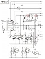
Terry please look at the input ,it's shorted ...... SGND it's not from -12V
Regards,Alex
Regards,Alex
Attachments

Last edited:

Had to lookup Sprint's abilities, some thing to be said about a layout package with no linkage/checking to a schematic or a netlist.
Not sure why anyone would use such a tool when you can use something with more functionality such as Eagle?
Not sure why anyone would use such a tool when you can use something with more functionality such as Eagle?
Last edited:
Well I do not use Eagle much either, I use orcad but that is not for free.
I tried Eagle and thought it was not very easy to learn either and I have used many cad pkgs.
Every cad tool has its own mind set, so they all take time, some times lots of time, to get into the head space for sure.
Just I hate to see folks use a cad pkg with limited or no checking between sch/layout, as it is very time consuming and a very error prone process. To be avoided unless know other solution exists.
I can help you learn eagle or anything else that we both can use. I know Jeff W is using diptrace which seems just as capable as Eagle, might want to give it try and see what you think.
Probably best to start a new thread on cad tool usage.
Last edited:
- Home
- Amplifiers
- Solid State
- DC Servo MOSFET Amplifier