Apex,
changing from BJT drivers to mosFET drivers: what else needed changing to make this work? Or is it a simple swap?
Are the drivers 610 & 9610? I can't read the font clearly, even expanded to full screen.
There is no any drivers on F100. IRF610/9610 are add to O/S, gate resistors on output mosfets are 100R instead 1k and resistor in Vbe multiplayer is 22k instead 4k7.
You must use IRF610/9610 drivers for 6 pairs... go to post #70
Regards
I go to post70 and the 610/9610 drivers are in the sch !There is no any drivers on F100. IRF610/9610 are add to O/S, gate resistors on output mosfets are 100R instead 1k and resistor in Vbe multiplayer is 22k instead 4k7.
I go to post70 and the 610/9610 drivers are in the sch !
Yes but schematic from post #70 is not F100.
Which Thread discusses the F100?
This is thread about F100 schematic from post #1.
Post1 sch is labeled A100
Where is the F100 Thread?
In post #7.
Any chance you can separate the different amplifiers, I have lost count of all the variations, and give each amplifier it's own Thread?
Any chance you can separate the different amplifiers, I have lost count of all the variations, and give each amplifier it's own Thread?
This thread is about DC Servo Mosfet Amplifier and all variations.
Hello guys
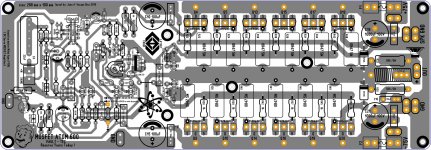
I know sometime I like to remake PCB and stuff like that but this design I know for sure will work fine as it is the F100 is on this PCB do not mind about the name I place on eh PCB is just that my artistic mind goes beyond my imagination jejejejeje 😛
if one day I build this one you guys for sure will know about it no problem, I do not have anything to hide I will share if all goes great but now I got to complete other projects that I have not test it yet, so meanwhile, I will take my time to make sure this PCB is 100% correct so if if some one want to try out I be happy to share PDF,Sprint 6 file also gebers if you don't know how to do it I'll place all in one zip folder so far with 6 pairs can give nice conservative wattage just enough to enjoy nice music I have build just a few amplifiers in diy not many but time teach me a lot from here and other areas in diyaudio.com
thanks to you guys I myself feel wonderful that I was able to learn even a bit more this pass few years, I'm not an amplifier designer nor a engineer and what I know now at least can get me go on maybe in a few years " I might create my own design who knows" but for now I'm just happy to know that they are many options to chose from, ok so I will continue with the layout maybe later will be 100% completed and I will share here same subject too 🙂
Best Regards
Juan
Attachments
Last edited:
thanks for the tip Alex
Good idea Alex MM I will fallow your advice thanks man
Regards
Juan
Not bad at all ,but you need to make some correction as I suggested below 🙂
Regards,Alex
Good idea Alex MM I will fallow your advice thanks man
Regards
Juan
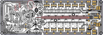
This is what I have so far I fallow Alex MM recommendation so now C25 is now close to IC pin 7 and C23 is now close to pin 4, and I split the center trace to have one of the traces feeding the NFB resistor R6 58K also I separate the resistors R7 and R8 away from C10, C24 and C26 now are 5 mm LS or pitch.
I will continue checking I'm slow I know jejejejejeje
Regards
Juan
I will continue checking I'm slow I know jejejejejeje
Regards
Juan
Attachments
I would run the NFB trace under R30, under D7, under R49....R25 then up and around Q12 , under C17
Then the output trace can become thick again. Repeat the output trace and any other very high current traces on the top side, so that you use two traces to carry the current.
i.e. both ends of R25 need top and bottom traces, Drain and Source of Q9 need top and bottom traces, F2 needs top and bottom traces, L1 needs top and bottom traces. All the spades (power, speaker, grounds) need top and bottom traces to make the fixing strong enough to survive push on and pull off of tight connectors.
I find that D4 & D5 work OK if 1n4003.
The current is not particularly high and even then it is transients that are higher. The one shot transient capability of a 1n4xxx is extremely high.
The voltage rating only needs to be greater than rail to rail voltage. Repeat the 1n4xxx across the supply to Power ground. These short out inadvertent mis-connections from the PSU and prevent damaging transistors, IF you use a Mains Bulb Tester for EVERY power ON after any modification.
I once swapped the zero volts and -ve supply of a dual supply to a chipamp that did not have these protection diodes. Result: a blown chip even though the voltages were well below the 80Vdc allowed by the self protecting chipamp. OH and I was too lazy to use the MBT !
oh man sorry to hear that about your chiamp blow out 🙁 yes the 1N4xxx for sure I will place on layout to avoid that human error connections that can happen to me too ! " I mean probably faster "
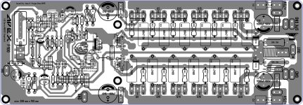
I had it like that top an bottom copper traces but I didn't not show it on the post #453 roger that, I will make those changes little bit by little bit at the time, and I'm thinking seriously later on to order just a few to try out I notice on simulation responds really well to high frequencies even I made a swap modification to BJT and also respond really well too, and yes totally I agree the spades connectors need to have top copper trace because those little devils they get really hard to remove after faston is installed and I have gorilla hands so ... 😛 , well I'm gonna do those changes I will take me time to do it right just like the AX-14T I did a couple a months ago same procedures, thanks Andrew for the tips recommendations
Best Regards
Juan
Last edited:
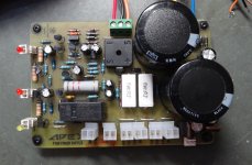
OK I have the PSU working. Here are the things I have tested so far. The output is -61.4V. +60.9V. There is a slight difference in the +-15V output too but that is less of an issue since it likely won't be used.
Now for the protection. 3Vdc won't trip it but 4.5vdc will but it takes 3 or 4 seconds. 12Vdc will trip it in about a second. Shorting the output does nothing. I don't know if that is true with an audio signal on it but I couldn't get it to trip by shorting it.
One other thing of note is that when you shut it down the - rail drains down but the positive doesn't. Maybe not an issue with an amp attached.
Next step is attaching the F100 and give it a try.
Blessings, Terry
Attachments
Hello mister Mile
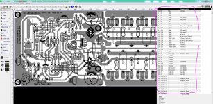
I have this crazy idea of adding more pair mosfet for the F100 so far I simulated as it is with original schematic, " I know is not accurate because is software simulation"
do I need to do any further modifications to able to use 6 pairs of mosfet ?
don't mind about the name Atom it will be always be F100 just with more pairs 🙂 ATOM 600 is just to identified my crazy ideas 😛
The PCB is not completed yet I still hunting for errors = erratas
Regards
Juan
With that many IRFP's ... at least use to-220's - wow ! 1330pf X 6.
Buffering the VAS (with another EF) would really improve things.
OS
this is unusually high unless there is a severely unbalanced load on the two supply rails. I typically see 0Vdc to 0.2Vdc difference in supply rails from my transformers. I think you need to investigate further............The output is -61.4V. +60.9V
This is too slow.........................Now for the protection. 3Vdc won't trip it but 4.5vdc will but it takes 3 or 4 seconds. 12Vdc will trip it in about a second. Shorting the output does nothing. I don't know if that is true with an audio signal on it but I couldn't get it to trip by shorting it.................
one or two seconds to trip for <2Vdc offset is usual for a competent offset detector. 4 to 5V of offset should give near instantaneous tripping, maybe <<0.5seconds.
10V offset should sound instantaneous.
This detector should NOT trip with a continuous 20Hz @ maximum sinewave at it's input.
Last edited:
With that many IRFP's ... at least use to-220's - wow ! 1330pf X 6.
Buffering the VAS (with another EF) would really improve things.
OS
I suggest modification in post #436
Regards
- Home
- Amplifiers
- Solid State
- DC Servo MOSFET Amplifier