Hello mister Mile
I have this crazy idea of adding more pair mosfet for the F100 so far I simulated as it is with original schematic, " I know is not accurate because is software simulation"
do I need to do any further modifications to able to use 6 pairs of mosfet ?
don't mind about the name Atom it will be always be F100 just with more pairs 🙂 ATOM 600 is just to identified my crazy ideas 😛
The PCB is not completed yet I still hunting for errors = erratas
Regards
Juan
You must use IRF610/9610 drivers for 6 pairs... go to post #70
Regards
Last edited:
You must use IRF610/9610 drivers for 6 pairs... go to post #69
Regards
thanks I will check now 🙂
Regards
Juan
God job! So far I have only tested it with a small PSU. +- 40vdc 300VA 6X4700uF. Sounds really good and plenty loud for indoor listening. I suppose if you want to use it in a club a bigger PSU would be warranted. I couldn't tell what frequencies your were testing with on your youtube video but they looked similar to what I see. Very square up to 20khz. 50khz starts getting rounded but that of course is way above human hearing.
I just etched the PSU and protection boards so I will try this PSU once I have it completed
Blessings, Terry
Hi Terry,
Do share your feedback on the PSU+Protect PCB. I have etched a couple of PCB but not yet soldered and tried on any amp.
regards
Prasi
Hi Terry,
Do share your feedback on the PSU+Protect PCB. I have etched a couple of PCB but not yet soldered and tried on any amp.
regards
Prasi
Will do. I am waiting on parts. As soon as they arrive I will test and report.
Bessings, Terry
i have built psu+protect in my Apex NX16, it detects overload, dc,it has mute function,clipping indication and turn-on delay. only i did not use it's psu,but combined it with Apex psu10.
Attachments
Last edited:
just to add - i measured voltage on PSU10 four years after first regulation and it was just as i adjusted it yesterday.
Hello guys
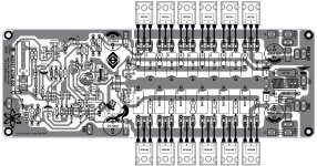
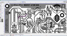
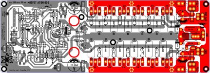
I will share Sprint file of the F100 Atom 600 I keep working on it and I fix some minor errors, I decide to share files so you guys can also check and help me out here with layout, so far I did try schematic on post #70 and it didn't work 'most be me making mistakes 🙁"
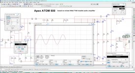
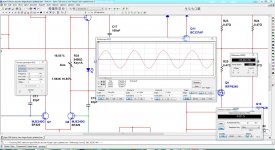
the layout you see here is still fallowing the F100 schematic no other modification is done only I add more pairs and still simulate really well on simulation, the rail I have to increased to 75V will be alright right there, "I think", the only downside I found is that Q3 and Q4 BF420 on the original schematic is that they are either obsolete or not available 🙁 so I simulated with MJE340G on both and it does work not as with the original part number but it does work, on PDF file I attached to this post Q7 and Q8 are the one that I use MJE340G, the bias I adjusted in a way testing with 20KHz to see if there is some kind of distortion for not been bias enough and the sweet spot on trim pot is 1.584K
this results might be different in real actual test
at 1KHz sine wave 1Vp @8 ohms load can give about 180W
at 1KHz sine wave 1Vp @4 ohms load can give about 385W
my goal here is not to get lot of power only just to have enough to enjoy low frequencies sometimes, I also read that adding more mosfet will help distribute that current between devices so they will work with less heat "this is what I think I might be wrong".
I was monitoring the rail current also to make sure is not over bias so it will not drain too much current " I apologize is this idea is not well explained"
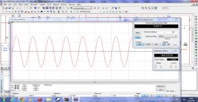
I'm trying to keep it working in a condition that it will not generate too much heat also check to keep it as low THD as possible I also simulated with square wave look normal.
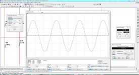
I was simulating with high frequencies it can go up to 35KHz and it will keep going no problem 🙂 I think this will be a great prototype to do, alright guys I hope you find this interesting maybe this will help others to gather ideas for new PCB creations.
feel free to updated and modified 🙂
note:
This PCB is not been tested yet
Regards
Juan
I will share Sprint file of the F100 Atom 600 I keep working on it and I fix some minor errors, I decide to share files so you guys can also check and help me out here with layout, so far I did try schematic on post #70 and it didn't work 'most be me making mistakes 🙁"
the layout you see here is still fallowing the F100 schematic no other modification is done only I add more pairs and still simulate really well on simulation, the rail I have to increased to 75V will be alright right there, "I think", the only downside I found is that Q3 and Q4 BF420 on the original schematic is that they are either obsolete or not available 🙁 so I simulated with MJE340G on both and it does work not as with the original part number but it does work, on PDF file I attached to this post Q7 and Q8 are the one that I use MJE340G, the bias I adjusted in a way testing with 20KHz to see if there is some kind of distortion for not been bias enough and the sweet spot on trim pot is 1.584K
this results might be different in real actual test
at 1KHz sine wave 1Vp @8 ohms load can give about 180W
at 1KHz sine wave 1Vp @4 ohms load can give about 385W
my goal here is not to get lot of power only just to have enough to enjoy low frequencies sometimes, I also read that adding more mosfet will help distribute that current between devices so they will work with less heat "this is what I think I might be wrong".
I was monitoring the rail current also to make sure is not over bias so it will not drain too much current " I apologize is this idea is not well explained"
I'm trying to keep it working in a condition that it will not generate too much heat also check to keep it as low THD as possible I also simulated with square wave look normal.
I was simulating with high frequencies it can go up to 35KHz and it will keep going no problem 🙂 I think this will be a great prototype to do, alright guys I hope you find this interesting maybe this will help others to gather ideas for new PCB creations.
feel free to updated and modified 🙂
note:
This PCB is not been tested yet
Regards
Juan
Attachments
-
Apex F100 Atom 600 updated 6-10-2015.pdf94.3 KB · Views: 301
-
 MOSFET F100 ATOM 600 small image.jpg721.7 KB · Views: 683
 -
 F100 with 6 pairs mosfet.JPG312.9 KB · Views: 385
 -
Mosfet atom 600 debugging.zip147.8 KB · Views: 267
-
 Apex F100 Atom 600 bias 1.5K.JPG282.5 KB · Views: 216
 -
 35KHz.JPG264.5 KB · Views: 210
Last edited:
Hi Juan,
I used KSA992/KSC1845 in place of the BF420/421 without issue. You might want to try those in you simulations.
I used KSA992/KSC1845 in place of the BF420/421 without issue. You might want to try those in you simulations.
Hi Juan,
I used KSA992/KSC1845 in place of the BF420/421 without issue. You might want to try those in you simulations.
oh thank for let me know 🙂
good thing the leads match yes
 !
!hey what you think about this layout isn't that cool 😉 ?
I guess I'm getting a bit better not like Alex MM but I'm getting there 😀
Regards
Juan
Attachments
Last edited:
It is singing. I used the KSA992/C1845 in place of BF420/421 and BC550/560 in place of BC327/337. I also installed a 10K trimmer in place of the 4k7 resistor. I have the bias set to 50mA. It runs a little hot with the music turned up. Probably be wise to mount them on separate heatsinks but this is fine for testing.Square waves look good and it clips nice.
Be sure if you build this that you use BC556 fpr the LTP. I used BC546 initially because that was the label on the schematic but it was in error. They are PNP so must be BC556.
Blessings, Terry
Terry, is it possible to share PCB layout in PDF format?
Regards,
Marcel
Hello guys
I will share Sprint file of the F100 Atom 600 I keep working on it and I fix some minor errors, I decide to share files so you guys can also check and help me out here with layout, so far I did try schematic on post #70 and it didn't work 'most be me making mistakes 🙁"
the layout you see here is still fallowing the F100 schematic no other modification is done only I add more pairs and still simulate really well on simulation, the rail I have to increased to 75V will be alright right there, "I think", the only downside I found is that Q3 and Q4 BF420 on the original schematic is that they are either obsolete or not available 🙁 so I simulated with MJE340G on both and it does work not as with the original part number but it does work, on PDF file I attached to this post Q7 and Q8 are the one that I use MJE340G, the bias I adjusted in a way testing with 20KHz to see if there is some kind of distortion for not been bias enough and the sweet spot on trim pot is 1.584K
this results might be different in real actual test
at 1KHz sine wave 1Vp @8 ohms load can give about 180W
at 1KHz sine wave 1Vp @4 ohms load can give about 385W
my goal here is not to get lot of power only just to have enough to enjoy low frequencies sometimes, I also read that adding more mosfet will help distribute that current between devices so they will work with less heat "this is what I think I might be wrong".
I was monitoring the rail current also to make sure is not over bias so it will not drain too much current " I apologize is this idea is not well explained"
I'm trying to keep it working in a condition that it will not generate too much heat also check to keep it as low THD as possible I also simulated with square wave look normal.
I was simulating with high frequencies it can go up to 35KHz and it will keep going no problem 🙂 I think this will be a great prototype to do, alright guys I hope you find this interesting maybe this will help others to gather ideas for new PCB creations.
feel free to updated and modified 🙂
note:
This PCB is not been tested yet
Regards
Juan
Can you post multisim file for post #70 schematic?
Regards
Can you post multisim file for post #70 schematic?
Regards
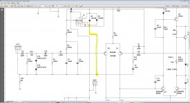
Yes of course maybe you can figure out what I did wrong, so far works really well with original F100 schematic with 6 pairs here are the file but this is version 14 of multisim I also include PDF 🙂
Regards
Juan
Attachments
Terry, is it possible to share PCB layout in PDF format?
Regards,
Marcel
Hi Marcell,
I am attaching it for iron transfer. If you need it for photo sense let me know.
This is Juan's layout.
Blessings, Terry
Attachments
missing connection
Hello guys
I have a missing connection on IC pin 3 to SIGND
I will leave Sprint 6 data here, I will continue hunting for errors my eyes are like this jejejejejeje
Regards
Juan
Hello guys
I have a missing connection on IC pin 3 to SIGND
I will leave Sprint 6 data here, I will continue hunting for errors my eyes are like this
jejejejejejeRegards
Juan
Attachments
Last edited:
Yes of course maybe you can figure out what I did wrong, so far works really well with original F100 schematic with 6 pairs here are the file but this is version 14 of multisim I also include PDF 🙂
Regards
Juan
F100 with mosfet drivers in multisim 14
Attachments

F100 with mosfet drivers in multisim 14
mister Mile can you post zip file with MS14 simulation when you get a chance 🙂 I do have space where you see the red circles
Regards
Juan
Attachments
I try to figure that out by myself mister Mile but I still can not get it to work correctly the image you post on #460 are not that clear "I use glasses" jejejejejeje

Regards
Juan
Regards
Juan
Hi Marcell,
I am attaching it for iron transfer. If you need it for photo sense let me know.
This is Juan's layout.
Blessings, Terry
Great! Thank you Terry..
Regards,
Marcel
Apex,F100 with mosfet drivers in multisim 14
changing from BJT drivers to mosFET drivers: what else needed changing to make this work? Or is it a simple swap?
Are the drivers 610 & 9610? I can't read the font clearly, even expanded to full screen.
- Home
- Amplifiers
- Solid State
- DC Servo MOSFET Amplifier