RE Replacements for IRF240/IRF9240
Hi Apex,
I found IRF540/IRF9540 fets. I have a +/-49V DC transformer with me. Can I use this transformer or is +/-45V the absolute max voltage for this amp with this fets. If so I will then continue my search for the proper fets. Any mods I can do to use this fets with my voltage?
Regards,
Macd🙂🙂🙂
IRF640/IRF9640 or IRF540/IRF9540 (with +/-45V DC max rail voltage) can be used.
Hi Apex,
I found IRF540/IRF9540 fets. I have a +/-49V DC transformer with me. Can I use this transformer or is +/-45V the absolute max voltage for this amp with this fets. If so I will then continue my search for the proper fets. Any mods I can do to use this fets with my voltage?
Regards,
Macd🙂🙂🙂
Hi Apex,
I found IRF540/IRF9540 fets. I have a +/-49V DC transformer with me. Can I use this transformer or is +/-45V the absolute max voltage for this amp with this fets. If so I will then continue my search for the proper fets. Any mods I can do to use this fets with my voltage?
Regards,
Macd🙂🙂🙂
What is AC voltage on transformer? You can use IRF540/IRF9540 with +/-49V DC rail voltage for usual home listening.
Regards
Replacements for IRF240/IRF9240
The AC voltage of my transformer is 35-0-35 Volts. After rectifier I get +/-49V. Is this okey? If I use force cooling like a fan, Is it okey......😱😱😱
Regards,
Macd
What is AC voltage on transformer? You can use IRF540/IRF9540 with +/-49V DC rail voltage for usual home listening.
Regards
The AC voltage of my transformer is 35-0-35 Volts. After rectifier I get +/-49V. Is this okey? If I use force cooling like a fan, Is it okey......😱😱😱
Regards,
Macd
+-49Vdc from a 35+35Vac transformer seems a bit low.
Is the transformer 230:35+35Vac?
Is your supply 220Vac when you measure the rectified DC voltage?
Are you using a single bridge rectifier with a CT transformer, or are you using dual bridge rectifiers with dual secondaries?
Is the transformer 230:35+35Vac?
Is your supply 220Vac when you measure the rectified DC voltage?
Are you using a single bridge rectifier with a CT transformer, or are you using dual bridge rectifiers with dual secondaries?
RE Replacements for IRF240/IRF9240
Yes, the transformer is rated at 220:35+35Vac. I am using a single bridge rectifier with my transformer. Only one secondary. I have measured my DC volts on output of transformer. +/-49V DC.
Macd
+-49Vdc from a 35+35Vac transformer seems a bit low.
Is the transformer 230:35+35Vac?
Is your supply 220Vac when you measure the rectified DC voltage?
Are you using a single bridge rectifier with a CT transformer, or are you using dual bridge rectifiers with dual secondaries?
Yes, the transformer is rated at 220:35+35Vac. I am using a single bridge rectifier with my transformer. Only one secondary. I have measured my DC volts on output of transformer. +/-49V DC.
Macd
The AC voltage of my transformer is 35-0-35 Volts. After rectifier I get +/-49V. Is this okey? If I use force cooling like a fan, Is it okey......😱😱😱
Regards,
Macd
Cooling is not problem, 100V drain to source voltage of IRF540/IRF9540 can be.
Regards
Step driver from H200 can be add to any amp for work in class H.
IRF3205/IRF4905 in TO220 case are the best choice for this class H step driver.
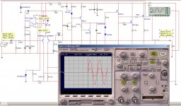
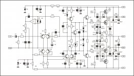
Apex seems i begin to love this amp 😀...the corrected clear schematic is this...
with different R14 values(tried 22k,30k,56k) and different supply voltage, circuit gave 50W-200W on 8ohm with great frequency response....
i try now to use opamp at front-end for smaller and simpliest pcb....
i tried many opamps so far (opa637,tl072....) but only the NE5532 gave a good result...60W/8Ohm
using +-50 supply and 30k(R14) on feedback...
i 'm not an expert on opamps so,any idea which other opamps to try?
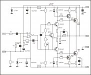
the circuit i try is this....
is there something that im missing?also the sine is not clear at output...seems to have much distortion...
An externally hosted image should be here but it was not working when we last tested it.
with different R14 values(tried 22k,30k,56k) and different supply voltage, circuit gave 50W-200W on 8ohm with great frequency response....
i try now to use opamp at front-end for smaller and simpliest pcb....
i tried many opamps so far (opa637,tl072....) but only the NE5532 gave a good result...60W/8Ohm
using +-50 supply and 30k(R14) on feedback...
i 'm not an expert on opamps so,any idea which other opamps to try?
the circuit i try is this....
An externally hosted image should be here but it was not working when we last tested it.
is there something that im missing?also the sine is not clear at output...seems to have much distortion...
An externally hosted image should be here but it was not working when we last tested it.
Last edited:
You can see PCB for this circuit in thread http://www.diyaudio.com/forums/solid-state/162043-mosfet-amplifier-irfp240-irfp9240-26.html post #253.
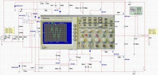
hmm..wasnt so easy as i though...
similated with no good results...~18W/8ohms 😕
with R12=1k...
similated with no good results...~18W/8ohms 😕
with R12=1k...
An externally hosted image should be here but it was not working when we last tested it.
oops....forgot it.....once more thanks for help...
fixed & worked
i changed values on R14 & R28 for ~110W/8Ohms
sine
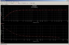
the frequency response wants a fix....and you know i got 110W at 1Khz...
fixed & worked
i changed values on R14 & R28 for ~110W/8Ohms
An externally hosted image should be here but it was not working when we last tested it.
sine
An externally hosted image should be here but it was not working when we last tested it.
the frequency response wants a fix....and you know i got 110W at 1Khz...
An externally hosted image should be here but it was not working when we last tested it.
no...nothing changed
An externally hosted image should be here but it was not working when we last tested it.
An externally hosted image should be here but it was not working when we last tested it.
This frequency response is to wrong to be real. In real life response is ok.
Attachments
Last edited:
- Home
- Amplifiers
- Solid State
- DC Servo MOSFET Amplifier