yeah thats true Apex!!!Not every one, beginners in DIY have better look on his design becouse of size and colours, my design confuse beginners, and there is much more beginners than experts, and there is some people who want just clone expensive brand to get better price for sale clone, and don't want learn anything.
Regards
some redsign from my self
So that the best from beginer to make expert....... & i've build some design from mr. mile like B500 standart, B500 TEF and H900- all is hand made, but some pict can't upload here bcause bad camera....
regards😉🙂
So that the best from beginer to make expert....... & i've build some design from mr. mile like B500 standart, B500 TEF and H900- all is hand made, but some pict can't upload here bcause bad camera....
regards😉🙂
Attachments
-
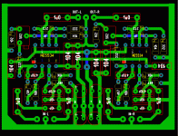
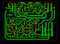
 B500 REV2-2.GIF185.2 KB · Views: 1,660
 -
 SUB BUFER-NE5534-For APEX D.GIF45.4 KB · Views: 561
 -
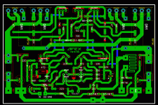
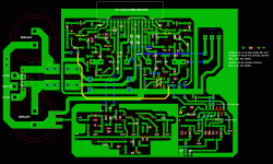
 PSU-Apex-In Progress.GIF108.5 KB · Views: 540
 -
 NX-1X.GIF106.7 KB · Views: 538
 -
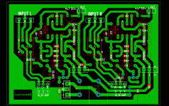 Balance inp-HH Pro Series.GIF63.9 KB · Views: 1,354
 -
 Apex-Protector.GIF97.6 KB · Views: 1,394
 -
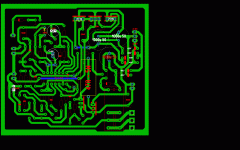
 Apex-NX14- in Progress.GIF76.4 KB · Views: 1,454
 -
 STK4192 II REV1.1.GIF185.1 KB · Views: 1,547
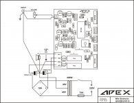
Old F100 schematic and pcb will be redesign.
hello Apex
I am from Iran
Circuit I've made you a quote.(post 122) But does not work.
PSU, but have not built the circuit.
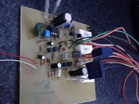
All components installed correctly. The schematic with transistor bf420 and bf421 board printed on it is different.
In case the printed installation pieces on the board. Voice was a little boost. But with very high noise and high loudspeaker diaphragm and coil it will be hot and very hot IRFP9240 MOSFET. The power output is 17 volts.
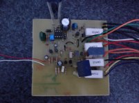
But when the transistor base, I just installed the schematic loudspeaker diaphragm remains high and the output voltage is 45 volts
Znrhay diode circuit within a few volts and watts are they?
ZY2V7:?
ZY15:?
ZF12:?
Attachments

Last edited:
CONNECT INPUT GND TO PSU GND...hello Apex
I am from Iran
Circuit I've made you a quote.(post 122) But does not work.
PSU, but have not built the circuit.
All components installed correctly. The schematic with transistor bf420 and bf421 board printed on it is different.
In case the printed installation pieces on the board. Voice was a little boost. But with very high noise and high loudspeaker diaphragm and coil it will be hot and very hot IRFP9240 MOSFET. The power output is 17 volts.
But when the transistor base, I just installed the schematic loudspeaker diaphragm remains high and the output voltage is 45 volts
Znrhay diode circuit within a few volts and watts are they?
ZY2V7:?
ZY15:?
ZF12:?
Dear friend, I realized. You mean is that instead of the PSU, gnd gnd input circuit connected to you?You must connect GND from transformer to input GDN signal. Understand?
How do I transistors and the base install according to the schematic or the photo on the PCB?
Thank you very much.This gnd wireing circuit from NX amp can be use for this amp.

How do I transistors installed? Like schematic or PCB?
Last edited:
Thank you very much.
How do I transistors installed? Like schematic or PCB?
This can help
Attachments

HELP ME
PLZ........
Post better pictures both sides of pcb with psu and wireing. There is no yellow LED on your pcb, it's part of bias circuit not signal led...
Last edited:
Thanks, all. Especially apex.
The problem was the LED and transistor.
Thank you very much.
I do not know how to thank.
Kiss for all

yahoo ID : masoud.lizard@att.net
ECA.ir
Signature:
DR.lizard from IRAN
Bye
The problem was the LED and transistor.
Thank you very much.
I do not know how to thank.
Kiss for all
yahoo ID : masoud.lizard@att.net
ECA.ir
Signature:
DR.lizard from IRAN
Bye
Last edited:
Thanks, all. Especially apex.
The problem was the LED and transistor.
Thank you very much.
I do not know how to thank.
Kiss for all
yahoo ID : masoud.lizard@att.net
ECA.ir
Signature:
DR.lizard from IRAN
Bye
Good news,
Regards
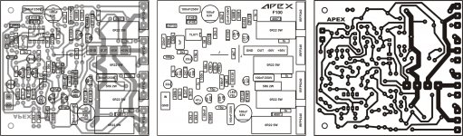
This old pcb with 5 pairs of outputs and protect can be redesign for FB400
I'm sorry if this was already mentioned or commented, but why use C6/47uF on feedback if there is a DC servo on that amp?
I'm sorry if this was already mentioned or commented, but why use C6/47uF on feedback if there is a DC servo on that amp?
I use TL071 instead pot for auto adjust DC offset, with C6 offset is +/-0.1mV and without C6 it's +/-1mV.
- Home
- Amplifiers
- Solid State
- DC Servo MOSFET Amplifier