As discussed in this thread, there are several possible causes for transformer mechanical hum, if your transformer is perfectly fine, e.g. no loose windings etc, than mains DC can be your problem here. My transformer is polish INDEL 600VA with 230V primaries and 2x24V secondaries. It hummed enaugh to annoy me and this DC filter indeed helpt to get rid of that noise a lot. It still humms a litle when it's just powered up, but humming goes away in short while, also this start-up hum is a lot quieter with DC filter present. Maybe it humms a little in normal opeartion too, but this hum is not in noticable levels, e.g. you have to put your ear very close to transformer to hear it and it is normal.
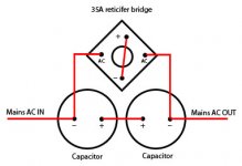
As for filter, there were many discussions about design. That's why there are many different schematics, photos etc. ESP article (the link I gave you in PM, discrete gave you here and I'm giving you now again) is very explainatory what goes where and why. My DC filter is based on that article. The choosing of parts in my case was using what I had laying around. Thats why theese where 6800uF 80V caps and 35A case mount with vires reticifer bridge. Design is simple:
* reticifer bridge's + and - wires is conected to each other
* reticifer's AC wires is conected to each of caps - terminals (one AC wire to one cap's -, second AC wire to other cap's - )
* capacitator's + terminals are conected to each other (+ve to +ve)
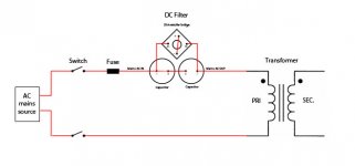
* filter is wired in series with transformer
Read that article and choose your parts wisely. Proceed with caution and be careful. Check your wirings many times before powering up anything. This is mains AC we are talking about, not a flashlight 9 volt battery. Schematic in article. Explained connection diagramm in atachments. Hopefully this will help.
As for filter, there were many discussions about design. That's why there are many different schematics, photos etc. ESP article (the link I gave you in PM, discrete gave you here and I'm giving you now again) is very explainatory what goes where and why. My DC filter is based on that article. The choosing of parts in my case was using what I had laying around. Thats why theese where 6800uF 80V caps and 35A case mount with vires reticifer bridge. Design is simple:
* reticifer bridge's + and - wires is conected to each other
* reticifer's AC wires is conected to each of caps - terminals (one AC wire to one cap's -, second AC wire to other cap's - )
* capacitator's + terminals are conected to each other (+ve to +ve)
* filter is wired in series with transformer
Read that article and choose your parts wisely. Proceed with caution and be careful. Check your wirings many times before powering up anything. This is mains AC we are talking about, not a flashlight 9 volt battery. Schematic in article. Explained connection diagramm in atachments. Hopefully this will help.
Attachments
Last edited:
As discussed in this thread, there are several possible causes for transformer mechanical hum, if your transformer is perfectly fine, e.g. no loose windings etc, than mains DC can be your problem here. My transformer is polish INDEL 600VA with 230V primaries and 2x24V secondaries. It hummed enaugh to annoy me and this DC filter indeed helpt to get rid of that noise a lot. It still humms a litle when it's just powered up, but humming goes away in short while, also this start-up hum is a lot quieter with DC filter present. Maybe it humms a little in normal opeartion too, but this hum is not in noticable levels, e.g. you have to put your ear very close to transformer to hear it and it is normal.
As for filter, there were many discussions about design. That's why there are many different schematics, photos etc. ESP article (the link I gave you in PM, discrete gave you here and I'm giving you now again) is very explainatory what goes where and why. My DC filter is based on that article. The choosing of parts in my case was using what I had laying around. Thats why theese where 6800uF 80V caps and 35A case mount with vires reticifer bridge. Design is simple:
* reticifer bridge's + and - wires is conected to each other
* reticifer's AC wires is conected to each of caps - terminals (one AC wire to one cap's -, second AC wire to other cap's - )
* capacitator's + terminals are conected to each other (+ve to +ve)
* filter is wired in series with transformer
Read that article and choose your parts wisely. Proceed with caution and be careful. Check your wirings many times before powering up anything. This is mains AC we are talking about, not a flashlight 9 volt battery. Schematic in article. Explained connection diagramm in atachments. Hopefully this will help.
This kind of serial connection by polarized caps always causes gripes by me. Have a look in the attachement. For me this looks much more better.
Attachments
As discussed in this thread, there are several possible causes for transformer mechanical hum, if your transformer is perfectly fine, e.g. no loose windings etc, than mains DC can be your problem here. My transformer is polish INDEL 600VA with 230V primaries and 2x24V secondaries. It hummed enaugh to annoy me and this DC filter indeed helpt to get rid of that noise a lot. It still humms a litle when it's just powered up, but humming goes away in short while, also this start-up hum is a lot quieter with DC filter present. Maybe it humms a little in normal opeartion too, but this hum is not in noticable levels, e.g. you have to put your ear very close to transformer to hear it and it is normal.
As for filter, there were many discussions about design. That's why there are many different schematics, photos etc. ESP article (the link I gave you in PM, discrete gave you here and I'm giving you now again) is very explainatory what goes where and why. My DC filter is based on that article. The choosing of parts in my case was using what I had laying around. Thats why theese where 6800uF 80V caps and 35A case mount with vires reticifer bridge. Design is simple:
* reticifer bridge's + and - wires is conected to each other
* reticifer's AC wires is conected to each of caps - terminals (one AC wire to one cap's -, second AC wire to other cap's - )
* capacitator's + terminals are conected to each other (+ve to +ve)
* filter is wired in series with transformer
Read that article and choose your parts wisely. Proceed with caution and be careful. Check your wirings many times before powering up anything. This is mains AC we are talking about, not a flashlight 9 volt battery. Schematic in article. Explained connection diagramm in atachments. Hopefully this will help.
allright, this explained this way i understand everything! And i know it's mains AC, so i am asking beforing doing anything 🙂 Very helpfull! thanks
but i have two more questions...
on this:
-filter is wired in series with transformer
what this mean? the live wire from AC comes from the socket then cuted and go to - cap and leave - cap on the other side to the transformer!
can i put this in a box metal or plastic.... like this: (from socket wall, then the filter on the metal/plastic box going to the iec plug on the active speaker?)
-And the other question ...
how to find the live wire on the cables? by color it's simple... but the plug turned 180º it's the neutral cable... is there a domestic way to find the live wire to put this filter?
ok thanks for all!
Just do it like in schematic, I don't have exact live and neutral markings in my country either.
@tiefbassuebertr - It's understandable, but... Well, it works well for about a month now... Also, what's the worst that can happen? Blown caps?
@tiefbassuebertr - It's understandable, but... Well, it works well for about a month now... Also, what's the worst that can happen? Blown caps?
Attachments
Last edited:
post 204 is the version I use.
The caps are 3300uF 16V low profile. I adopt between 4 and 7 parallel caps to give the required 50Hz impedance at normal maximum AC current draw. Gives a flat pack arrangement that can be squeezed into some Mains SAFE area/volume.
Remember the diodes pass the abnormal peak currents, eg. start up surge and misuse of the amplifier.
I'm a newbe & this is my first post
I joined the forum as it suits my hobby(s) & interest in DIY & experimenting
This fills some of my retirement time after 40+ years in electrical & refrigeration R&D & field trouble shooting around the world
I designed & built the attached filter schematic to help with a minor mains DC issue that causes my Naim system to hum more than it should. All my boxes are quiet(ish) except the CDP. But the main problem I had with DC was that the hum tone & level would change momentarily for for short periods, this is distracting.
The filter is placed in my 8 way power strip & filters 6 of the outlets. Its sized for current draw with 230v 50Hz up to 750VA.
The filter fixed the DC issue completely, but it did not stop the CDP transformer from humming. Its just slightly quieter but the DC caused tone variations are gone.
The message here is that no filter will stop a transformer that is inherently noisy from humming.
An externally hosted image should be here but it was not working when we last tested it.
Is there any way to find what's the live wire, instead of the neutral?
because of the 180º turn of cable IEC?
I know there are some piece of equiment that does that... but i want a domestic way to find that?
Other thing... i found some 800v 35A bridge rectifier in my country!.
Can i use that 800v bridge rectifer? Or has to be 400v? Don't know...
Ok. I got enough info i a am searching the stuff to buy!
I will cute the power wire that comes from the wall socket and goes to the active speaker (put that filter on a plastic box or metal) and then the rest of the cable goes to the IEC plug on the active speaker!
And hope not CABUMMMMMMMM or smell... just waiting for the hum goes away!
My speakers are:
Samson Audio - Live! 1215
Thanks you all!
because of the 180º turn of cable IEC?
I know there are some piece of equiment that does that... but i want a domestic way to find that?
Other thing... i found some 800v 35A bridge rectifier in my country!.
Can i use that 800v bridge rectifer? Or has to be 400v? Don't know...
Ok. I got enough info i a am searching the stuff to buy!
I will cute the power wire that comes from the wall socket and goes to the active speaker (put that filter on a plastic box or metal) and then the rest of the cable goes to the IEC plug on the active speaker!
And hope not CABUMMMMMMMM or smell... just waiting for the hum goes away!
My speakers are:
Samson Audio - Live! 1215
An externally hosted image should be here but it was not working when we last tested it.
Thanks you all!
targeting, if you are asking those questions, you should not be working with electricity.
The filter can be connected in live or neutral, reversing the cable connection will not harm it.
The bridge needs to be same or higher rated voltage as your supply e.g. if you have 220v, then a 250v or higher bridge is OK.
Remember this will not stop a transformer that is already & naturally noise
The filter can be connected in live or neutral, reversing the cable connection will not harm it.
The bridge needs to be same or higher rated voltage as your supply e.g. if you have 220v, then a 250v or higher bridge is OK.
Remember this will not stop a transformer that is already & naturally noise
targeting, if you are asking those questions, you should not be working with electricity.
The filter can be connected in live or neutral, reversing the cable connection will not harm it.
The bridge needs to be same or higher rated voltage as your supply e.g. if you have 220v, then a 250v or higher bridge is OK.
Remember this will not stop a transformer that is already & naturally noise
ok,then for the conection on live or neutral cable.
the rectifier bridge can be 800v if i got mains 230v coming from the wall, or is it better to be on the 250v range? i mean if bigger will be safer, or worse?
"Remember this will not stop a transformer that is already & naturally noise"
-what do you mean by these? that for those speakers i will not see differences on the mechanical noise hum? naturally noise, means?
Transformers all make "mechanical" noise, some its not audible, some is loud
DC on the mains supply makes it sound at a higher level making even a quiet traffo noisy
DC on the mains supply makes it sound at a higher level making even a quiet traffo noisy
the rectifier bridge can be 800v if i got mains 230v coming from the wall, or is it better to be on the 250v range? i mean if bigger will be safer, or worse?
Use that 800V 35A bridge reticifer you mention earlyer and you'll be just fine. I'm using in my DC filter 800V 35A bridge too for 220V mains.
100A High Power Rectifier Diodes with Forward Voltage Drop >200mV wanted
This kind of serial connection from polarized caps isn't the right way from my view. And the version with two anti paralleled caps also not. What happens internal by both caps in both cases, if there is very high current flow (e. g. while inrush current of a big toroidal transformer) especially by the cap, that works in the reverse mode ??
Have you also checked the topology from post 202?
the description to this circuit is there:
DC-Blocker - Scintilla-buizenversterkers
But I will try another version. Therefore I am looking to high power rectifier diodes, where the forward voltage drop (usually between 0V6 and 0V7) is as low as possible, at best below 0V3 like usual at very small signal germanium diodes (schottky diodes forward voltage drop are arround 0V4 until 0V5).
Who knows appropriate types ?
Also of interest for me are zener's, where the usually present 0V7 in the wrong direction also is low as possible, i. e. arround 0V2 (and at the same time the exactly behaviour in the reverse direction with "ZENER" effect).
I need this devices to realize a new approach of a dc filter for blocking DC voltages up to 6 volts.
Thank you for your efforts.
I'm a newbe & this is my first post
I joined the forum as it suits my hobby(s) & interest in DIY & experimenting
This fills some of my retirement time after 40+ years in electrical & refrigeration R&D & field trouble shooting around the world
I designed & built the attached filter schematic to help with a minor mains DC issue that causes my Naim system to hum more than it should. All my boxes are quiet(ish) except the CDP. But the main problem I had with DC was that the hum tone & level would change momentarily for for short periods, this is distracting.
The filter is placed in my 8 way power strip & filters 6 of the outlets. Its sized for current draw with 230v 50Hz up to 750VA.
The filter fixed the DC issue completely, but it did not stop the CDP transformer from humming. Its just slightly quieter but the DC caused tone variations are gone.
The message here is that no filter will stop a transformer that is inherently noisy from humming.
An externally hosted image should be here but it was not working when we last tested it.
This kind of serial connection from polarized caps isn't the right way from my view. And the version with two anti paralleled caps also not. What happens internal by both caps in both cases, if there is very high current flow (e. g. while inrush current of a big toroidal transformer) especially by the cap, that works in the reverse mode ??
Have you also checked the topology from post 202?
the description to this circuit is there:
DC-Blocker - Scintilla-buizenversterkers
But I will try another version. Therefore I am looking to high power rectifier diodes, where the forward voltage drop (usually between 0V6 and 0V7) is as low as possible, at best below 0V3 like usual at very small signal germanium diodes (schottky diodes forward voltage drop are arround 0V4 until 0V5).
Who knows appropriate types ?
Also of interest for me are zener's, where the usually present 0V7 in the wrong direction also is low as possible, i. e. arround 0V2 (and at the same time the exactly behaviour in the reverse direction with "ZENER" effect).
I need this devices to realize a new approach of a dc filter for blocking DC voltages up to 6 volts.
Thank you for your efforts.
Last edited:
Tief,
you have chosen to show/use the wrong implementation of the bridge rectifier for your DC blocker.
Short the ~ to ~
Short the + to -
Connect mains incomer to ~
Connect outgoing mains from + or - (they are both connected).
This implementation puts the diodes in the bridge in parallel rather than the series connection you show.
The double shorted version has half the Vdrop and double the current capacity cf. the single shorted version.
Hi Tief.
I am not sure if your post is a statement or a question. But whatever, this is my thinking.
The DC block filter running in an AC system will require either
(1) Non-polarised capacitor (not practical for size considerations)
(2) 2 or more polarised caps in parallel non-polar config
(3) 2 or more polarised caps in series non-polar config
I am not sure series or parallel is that important & am not dramatically persuaded one way or other.
However I opted for my method for longevity reasons:
If two, same-value, electrolytic capacitors are connected in series (back-to-back) with the positive terminals or negative terminals connected, this results in effectively a single capacitor that is non-polar, but the downside is it gives half the capacitance of each of the individual components.
But it gives 2x upsides:
(1) Doubles the operating voltage – 16v becomes 32v or you can safely go even lower as 2x series diodes limit voltage across the cap to 1.4v – but practically 1.3v
(2) Maximises ripple current through the cap assembly - As we all know electrolytic caps will withstand a small reverse voltage (around 1V is typical), this series connection method doubles that value & achieves similar or even higher levels of longevity, probably reaching many years even when permanently running.
Additionally I designed my filter for 750VA to permit a power cut followed by uncontrolled switch on.
But it is actually running a number of transformers - the largest is 400VA - that collectively do not exceed that value at inrush, plus they are normally not switched on simultaneously.
In-rush aside, the filter is running with 95% reserve when my audio system is on idle & aprx 85% reserve when used at disco level volume.
The Circuit from which post ?Tief,
you have chosen to show/use the wrong implementation of the bridge rectifier for your DC blocker.
Short the ~ to ~
Short the + to -
Connect mains incomer to ~
Connect outgoing mains from + or - (they are both connected).
This implementation puts the diodes in the bridge in parallel rather than the series connection you show.
The double shorted version has half the Vdrop and double the current capacity cf. the single shorted version.
I haven't until now a clearly statement to (2) and (3), because I am also not sure about the behaviour while high current flows.Hi Tief.
I am not sure if your post is a statement or a question. But whatever, this is my thinking.
The DC block filter running in an AC system will require either
(1) Non-polarised capacitor (not practical for size considerations)
(2) 2 or more polarised caps in parallel non-polar config
(3) 2 or more polarised caps in series non-polar config
I am not sure series or parallel is that important & am not dramatically persuaded one way or other.
about
http://www.epcos.com/web/generator/...__en.pdf;/PDF_GeneralTechnicalInformation.pdf
there isn't to read about "back to back" serial connection.
I have found only this statement about
Electrolytic capacitors
The only downside for electrolytic capacitors is that their metal-to-metal oxide interface is a rectifying contact. That is, it is a good insulator only in one direction, and in the other it conducts electricity. That is why electrolytic capacitors are non-polar, and the only way that non-polar electrolytic capacitors can be created is to use two oxide films back to back.
Last edited:
Andrew, it's better to have the diodes in series because then the blocking will get more effective.Tief,
you have chosen to show/use the wrong implementation of the bridge rectifier for your DC blocker.
Short the ~ to ~
Short the + to -
Connect mains incomer to ~
Connect outgoing mains from + or - (they are both connected).
This implementation puts the diodes in the bridge in parallel rather than the series connection you show.
The double shorted version has half the Vdrop and double the current capacity cf. the single shorted version.
In my design I have three diodes in series.
Tiefbassuebertr,
I have implemented this circuit in all of my amps that utilizes toroidal transformers for a number of years now, and I concur with Mike B, it works perfectly and removes mechanical noise due to dc bias of mains perfectly.
Nico
I have implemented this circuit in all of my amps that utilizes toroidal transformers for a number of years now, and I concur with Mike B, it works perfectly and removes mechanical noise due to dc bias of mains perfectly.
Nico
I will accept that it is a design decision depending on the operating criteria to whether 700mV or 1400mV or 2100mV of bypass voltage is allowed across the diodes.Andrew, it's better to have the diodes in series
I cannot accept that it is better to have series connected diodes when Tief is is asking about excessive diode Vdrop and suggesting the solution is massive diode current capability.
The designer chooses to suit the conditions.
Taking the point made by Mikeb that 1000mV of reverse voltage is tolerable on a polarised electrolytic, then increasing the bypass voltage to double or triple value cannot be good for paralleled electrolytics.
However, series back to back electrolytics behave differently and in this wiring arrangement your double or triple diode solution allows smaller capacitors to be used for the same AC current flow that does not bypass through the diodes.
Last edited:
- Home
- Amplifiers
- Solid State
- DC filter