from what you are saying and asking it appears you do not understand what the DC blocker is doing nor do you understand it's limitations and what needs to be done to make it's adoption safe..... talk about reverse voltage (forward Voltage?) of the capacitor itself;
thats why we want to put the caps back to back in series not in parallel like Bryston.
So putting the caps in series bypasses this danger of having max of about 1-1.5 Vf of the cap?
I chose high power diodes that combined will form about 2.2 Vf (~1.1 each); is it too high for the caps (same question)?.
Go back and re-read the DC blocker's operation. When some components pass current and when other components pass current.
This is a LIVE circuit. You must ensure you can assemble and install it safely.
If you have any doubts about it's assembly I cannot see how you can install it safely !!!!
Thanks for replying Andrew.
Worry not, I've worked with tube amps and high voltage before.
Just the back to back cap that forms bi-polar cap, reverse bias is not quite clear.
Also the total Ripple current of these caps in series would be.
Worry not, I've worked with tube amps and high voltage before.
Just the back to back cap that forms bi-polar cap, reverse bias is not quite clear.
Also the total Ripple current of these caps in series would be.
Sorry for double posting (I can't edit previous posts).
I understand the formulas involved.
Using Ohm law I calculated that for 10A and 2 Vf of the diodes it would be 0.2 ohm of resistance.
Using 1/(2*Pi*50*0.2) I got ~16000uF.
So at least two 32000uF caps in parallel (back to back).
I plan to use 47000uF 16v Nichicon with 6.93A ripple Current each.
The diodes I use:
http://www.rectron.com/data_sheets/10a05-10a10.pdf
So the quiestions I posted are still valid.
Thanks
bump. 😱
Is it worth building a DC blocker with a DC offset of 20mV on the mains?
I measuer across the cap with 100k and 10uF.
My studio monitors hum.
Each is 110W.
Is it worth building a DC blocker with a DC offset of 20mV on the mains?
I measuer across the cap with 100k and 10uF.
My studio monitors hum.
Each is 110W.
listen to the mechanical hum of your transformer and what it does to the chassis of your equipment.
Fit a temporary DC blocker and compare results.
Fit a temporary DC blocker and compare results.
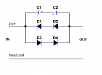
1n5401, or 5402, or 5403, or 5404. Two in series in each direction (4 total).
10mF to 20mF 16V electrolytic. Two in series +ve to +ve.
The 10m to 20m capacitance can be a parallel bank of lower value capacitors. They might be cheaper. I use 3300uF 16V, 5 in parallel in each direction for a net 8m25F which has an impedance of ~0.4 ohm at 50Hz.
2Aac will generate ~1.1Vpk across the caps and diodes. The diodes should not pass when 2Aac is being drawn.
That allows ~500W to be consumed and the bypass diodes should not pass.
Current pulses exceeding 3Apk will bypass via the diodes.
check out this URLs:What exact diodes and cap ratings shoud I use to bild a DC-filter for 600VA transformer?
Mains DC and Transformers
http://www.diyaudio.com/forums/powe...t-buzzing-toroid-transformers-what-right.html
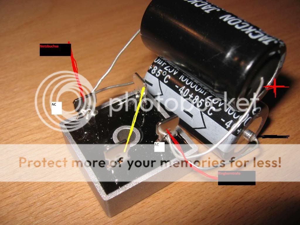
Normally when I do such things I join the two minus. This just because the Capacitor chassis normally is that one and this can prevent shorts if they touch by chance putting them really close. There still are around non -insulated ones, or the insulator may fail .1n5401, or 5402, or 5403, or 5404. Two in series in each direction (4 total).
Two in series +ve to +ve.
Not really important, nor necessary, just I belive between the two choices, that's the more logical.
Last edited:
DC Filter Trap placement?
Hi Everyone,
I have not built my DC Filter Yet, but am ready to order the parts. My question is dose the DC Filter Trap applied to both AC lines or just one, the design I am following has identified three AC lines into the power supply, 1. DC Filter Trap, 2. Neutral meaning a streight wire through to other circuits you might wish, 3. Protective Earth as a strieght wire through to other circuits ?
Intuetively I am concedering putting the DC Trap on both 120VAC lines, is this just a waist of money for parts and unnessessary loss of 2-3 more Volts DC output of the power supply for my four Aleph J-X monoamps ?
THank you for any help you can refer me to, even other schematics for a DC Filter Trap, because I am open to new ideas.
Ian
The transformer had two primary connections therefore you will need something in series. Yes, one filter is enough.
The Safety Ground wire is connected to Mother Earth and one end and to your chassis at the other. No significant current should flow through this wire. (see Andrew's post above)
The Neutral wire is connected to Mother Earth and one end and to your power transformer at the other end. The Neutral wire must NOT be connected to your chassis.
Your Power Supply does not use the Safety Ground as a current path.
Hi
Are you saying that the positive and negative outputs, from the two bridge recifiers I am using in my power supply, that are connected to each other, leaving the positive and negitive rails from the other outputs from the two bridge rectifiers, should not be connected to the amplifiers chassis ground ?
Thank You For Your Help
Ian
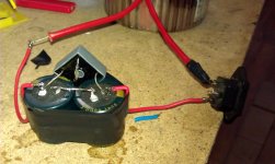
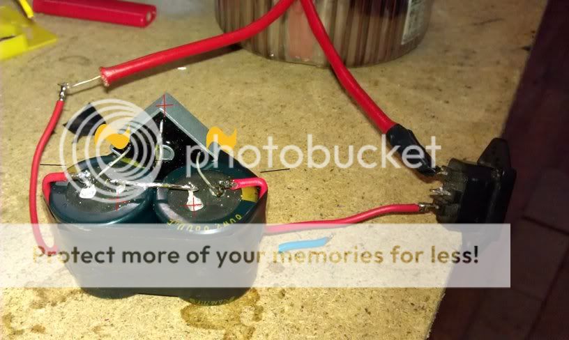
Did mine MacGyver-style (because of duct tape) with 35A bridge reticifer and two 6800uF 80V caps. Works good, transformer noise went down a lot.
hello!
i am from portugal hand have two profissional active speakers from samson this ones...
Samson Audio - Live! 1215
fact is... when powering them they hum... even without any signal XLR cable. SO i got transformer noise or mechanycall noise, right?
i like this picture i saw above. Very educative, raw but simple just the way i like it!
I am a newbie on electronics... but have skills to solder. What should i buy to get rid of that hum?? and how to install it?
Thoise speakers are capable of 500wrms each!
for what i see is this right? the simbols?
-In this form the caps are wired paralel? why?
-and on this they are wired in sereis, why?
What one of theses will remove the HUM mechanical sound of transformers?
i got an active speakers like i said on the last post... and when powering them i got hum... and the hum comes from inside the boxes... transformer.
will any of these pictures solution for my problem... and why the diferencçes on caps?
The upper pic shows the caps wired in series with +ve to +ve.
The lower pic (filter 94) shows the caps wired in parallel. The current can through one or other or through both. There are three distinct routes for the current to flow, through the diode bridge, through the upper capacitor through the lower capacitor.
The lower pic (filter 94) shows the caps wired in parallel. The current can through one or other or through both. There are three distinct routes for the current to flow, through the diode bridge, through the upper capacitor through the lower capacitor.
- Home
- Amplifiers
- Solid State
- DC filter