Canned means factory built in an all-metal enclosure which looks like a can. See attachment.
_
And I indeed got a noise reduction using a Schaffner FN 2090 (a 16A model, before the whole power strip - I will later build it in a star connected power distributor with a DC blocker inside - i have some small amount of DC and both transformer and speaker buzz, even though extremely low, can vary depending on the time of the day)
Roberto
interference enters via EVERY cable that enters the enclosure.
If any of those cable are "exposed" inside the enclosure then they emit interference, especially if they are single cables/wires/traces rather than a flow and return pair.
You should trap interference at the cable entry.
That interference must be taken to the enclosure and thence by capacitance to "EARTH". It is this important route that requires the "canned" filter to be at the cable entry. This leaves no "exposed" cable before the filter and the can is bolted and/or electrically connected to enclosure to conduct the interference to EARTH.
You are right, if the cable between the filter and the enclosure entry is not shielded. What if the cable is shielded and the shield is only connected at the filter at the filter side, not to the ground at the device side? Intuitively, this should give better interference rejection than an unshielded cable.
Roberto
In most cases EMI filters produce inferior sound to my ears.
This because most are designed for low currents. Lucio Cadeddu of TNT audio Anti-RFI filters for the mains warned about using them on power amps
Roberto
Agree too, but sometimes DC can have other unpleasant consequences: when i installed my Buffalo Dac i was very pleased with the sound only to find out it would loose sync each time i switched the lights- very annoying. TP support forums hinted at a DC blokker to prevent this and I installed one. No more unlocks. This was in a recent appartement, electrical wiring was fine.
This is indeed weird, but it happened recently that when my wife was turning on a food mixer, my Gustard X20U DAC would unlock. The kitchen is on the other side of the wall where I have my audio equipment. It may be DC or something else (airborne EM noise), but the result was replicable.
Roberto
Assembled one more Main AC filter unit and that time is for my TV/Movie gear. Subjectively, TV picture is sharper and no pixels artifacts observed without main AC filter. Can’t say anything yet about color changes since it is hard to memories and compare. I will test my Blue Ray and Receiver in-action over this weekend.
The changes in this unit vs. my first filter are:
a. No L<-->N electrolytic caps.
b. CMCs and cap are soldered on PCB designed by Keantoken and made by DertyPCB.
c. Deno GND chokes are installed on every receptacle vs. single one for all receptacles in my first unit.
Personal thanks to Destroyer OS and Keantoken for tremendous help.
What's the purpose of the DNG choke? I have seen designs without it, and I am wonder what the downside would be.
Roberto
Andrew, you are not quite right here. A sine wave which has for instance the positive peak cut a bit will end up in harmonics PLUS a DC component. A good example to use a hairdryer at half speed (a diode in series). The DC filter doesn't improve the wave form but will at least remove the DC component.The DC blocker does not actually block a DC offset. There is no DC to block. Thus no DC to measure.
It seems to be a filter that reduces the asymmetry in the AC waveform.
If you are reading 4Vdc, then I wonder what that reading is actually telling you.
I'm not the expert, but I don't think what you are arguing to be correct.Andrew, you are not quite right here. A sine wave which has for instance the positive peak cut a bit will end up in harmonics PLUS a DC component. A good example to use a hairdryer at half speed (a diode in series). The DC filter doesn't improve the wave form but will at least remove the DC component.
An asymmetric AC waveform is a pure AC wave plus lots of harmonics that are not symmetric.
That is not the same as DC + harmonics.
But irrespective of whether there is a real DC component in the asymmetric waveform or not, the Capacitor does reduce the saturation effect in the transformer core.
The transformer behaves as if it had a DC component (the +ve core flux does not balance the -ve core flux) in the current flow and the capacitor seems to work in reducing the flux asymmetry.
Yes, H.Ott tells us that "exposed" cable should be shielded to contain the interference and that this shield should be connected at BOTH ends if it is expected to work at the higher interference frequencies.You are right, if the cable between the filter and the enclosure entry is not shielded. What if the cable is shielded and the shield is only connected at the filter at the filter side, not to the ground at the device side? Intuitively, this should give better interference rejection than an unshielded cable.
Roberto
H.Ott tells us that a shield connected at one end only only works effectively at low frequencies.
Hello,
I've read through the thread and want to make a DC blocker, as per the Rod Elliott info.
I plan to use the Fairchild GBPC 35A bridge rectifier for the diode source.
Could someone tell me what the heat it gives off in this circuit is like? i.e. is it OK to mount it to an ABS enclosure or will it need to be a metal one?
Also, I couldn't determine a clear answer for the minimum acceptable capacitor voltages?
I intend to use it on a variety of guitar preamps and power amps that I don't have the transformer specs for. And it may be used in varying locations, in England, where I don't know what level of DC may be on the mains.
Thanks
The bridge should run pretty cool in real world applications i.e a class AB amp delivering music. If you are power testing an amp e.g. delivering 100 watts RMS into 8 ohms then its going to get hotter. Same applies if its a class A amp with high current draw.
A good guide would be to suggest it won't run very much hotter than the bridge in the amp itself.
Cap voltage rating can be as low as 6.3 volts because each cap only sees 'two diode's worth' of voltage at most. That's only around a couple of volts even at very high current.
A good guide would be to suggest it won't run very much hotter than the bridge in the amp itself.
Cap voltage rating can be as low as 6.3 volts because each cap only sees 'two diode's worth' of voltage at most. That's only around a couple of volts even at very high current.
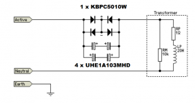
I am using four Digikey part# 493-1517-ND capacitors for my DC blocker. These are Nichicon UHE1A103MHD6 devices: 10,000 uF, 10V, 4.2 amperes ripple current, 14 milliohms ESR, 8000 hours lifetime @ 105C. I have also selected a 50 ampere, 1000 volt bridge rectifier with wire leads ("W" suffix) instead of fast-on spade connectors. I will bolt a small heatsink to the bridge rectifier to help it dump the (V x I) power it dissipates. I've annotated these part numbers onto Rod Elliott's schematic, below.
Maybe you can build an LTSPICE simulation of the incoming AC mains, the DC blocker, your power transformer, your rectifiers, your DC filter capacitors, and a load resistor that draws the maximum current your power supply will ever be called upon to provide. Then you could have LTSPICE plot the power dissipated in the DC blocker, and the voltage across the DC blocker capacitors. These might help you decide how much heatsinking you want (if any!) for the DC blocker bridge rectifier, and what voltage rating you want for the DC blocker capacitors.
_
Attachments
The capacitors of a DC blocker pass the AC current.Hello,
I've read through the thread and want to make a DC blocker, as per the Rod Elliott info.
I plan to use the Fairchild GBPC 35A bridge rectifier for the diode source.
Could someone tell me what the heat it gives off in this circuit is like? i.e. is it OK to mount it to an ABS enclosure or will it need to be a metal one?
Also, I couldn't determine a clear answer for the minimum acceptable capacitor voltages?
I intend to use it on a variety of guitar preamps and power amps that I don't have the transformer specs for. And it may be used in varying locations, in England, where I don't know what level of DC may be on the mains.
Thanks
The diodes are there to bypass the capacitors during overload.
The diodes should pass ZERO current during normal operation.
They will run COLD.
I have used 1n5402 diodes and they never get warm. They are always cold.I am using four Digikey part# 493-1517-ND capacitors for my DC blocker. These are Nichicon UHE1A103MHD6 devices: 10,000 uF, 10V, 4.2 amperes ripple current, 14 milliohms ESR, 8000 hours lifetime @ 105C. I have also selected a 50 ampere, 1000 volt bridge rectifier with wire leads ("W" suffix) instead of fast-on spade connectors. I will bolt a small heatsink to the bridge rectifier to help it dump the (V x I) power it dissipates. I've annotated these part numbers onto Rod Elliott's schematic, below.
Maybe you can build an LTSPICE simulation of the incoming AC mains, the DC blocker, your power transformer, your rectifiers, your DC filter capacitors, and a load resistor that draws the maximum current your power supply will ever be called upon to provide. Then you could have LTSPICE plot the power dissipated in the DC blocker, and the voltage across the DC blocker capacitors. These might help you decide how much heatsinking you want (if any!) for the DC blocker bridge rectifier, and what voltage rating you want for the DC blocker capacitors.
_
I think the aim of the diodes is for in-rush current capability, and possibly even a fault rating, such that the diodes should stay healthy no matter what the prospective current could get to from the AC mains supply.
Hence the recommendation to use the bigger bridges as a catch all, even for transformers with very low primary winding resistance and mains supplies with high fault current capability.
Hence the recommendation to use the bigger bridges as a catch all, even for transformers with very low primary winding resistance and mains supplies with high fault current capability.
That's high I understand it too, bridge is just to handle inrush.
My caps are 50V, 4700uf. I fuse my units at 4A which is a 800W capacity.
My caps are 50V, 4700uf. I fuse my units at 4A which is a 800W capacity.
I thought the bridge was to handle overloads for long enough to blow a fuse or trip a breaker. Hence it needs to be a big bridge but doesn't need heatsinking?
The bridge should run pretty cool in real world applications i.e a class AB amp delivering music. If you are power testing an amp e.g. delivering 100 watts RMS into 8 ohms then its going to get hotter. Same applies if its a class A amp with high current draw.
A good guide would be to suggest it won't run very much hotter than the bridge in the amp itself.
Cap voltage rating can be as low as 6.3 volts because each cap only sees 'two diode's worth' of voltage at most. That's only around a couple of volts even at very high current.
I am using four Digikey part# 493-1517-ND capacitors for my DC blocker. These are Nichicon UHE1A103MHD6 devices: 10,000 uF, 10V, 4.2 amperes ripple current, 14 milliohms ESR, 8000 hours lifetime @ 105C. I have also selected a 50 ampere, 1000 volt bridge rectifier with wire leads ("W" suffix) instead of fast-on spade connectors. I will bolt a small heatsink to the bridge rectifier to help it dump the (V x I) power it dissipates. I've annotated these part numbers onto Rod Elliott's schematic, below.
Maybe you can build an LTSPICE simulation of the incoming AC mains, the DC blocker, your power transformer, your rectifiers, your DC filter capacitors, and a load resistor that draws the maximum current your power supply will ever be called upon to provide. Then you could have LTSPICE plot the power dissipated in the DC blocker, and the voltage across the DC blocker capacitors. These might help you decide how much heatsinking you want (if any!) for the DC blocker bridge rectifier, and what voltage rating you want for the DC blocker capacitors.
_
The capacitors of a DC blocker pass the AC current.
The diodes are there to bypass the capacitors during overload.
The diodes should pass ZERO current during normal operation.
They will run COLD.
I have used 1n5402 diodes and they never get warm. They are always cold.
I think the aim of the diodes is for in-rush current capability, and possibly even a fault rating, such that the diodes should stay healthy no matter what the prospective current could get to from the AC mains supply.
Hence the recommendation to use the bigger bridges as a catch all, even for transformers with very low primary winding resistance and mains supplies with high fault current capability.
That's high I understand it too, bridge is just to handle inrush.
My caps are 50V, 4700uf. I fuse my units at 4A which is a 800W capacity.
I thought the bridge was to handle overloads for long enough to blow a fuse or trip a breaker. Hence it needs to be a big bridge but doesn't need heatsinking?
Thanks for all the info, chaps, just what I wanted.


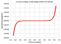
I connected the 50 ampere bridge rectifier as shown in post #151 and put it onto a curve tracer. It is pleasant to observe that for the level of mains DC offset mentioned as an example on Rod Elliott's website (275 mV), bridge current is zero microamperes, at least at room temperature. The four big ole bohunker diodes inside the bridge, seem to have negligible amounts of leakage at plus or minus 275 millivolts of bias.
_
_
Attachments


- Home
- Amplifiers
- Power Supplies
- DC blockers and mains filters