This is one more argument for using machine-made non-exotic capacitors. Tight winding, firmer dielectrics. Something like a Wima MKP will waste a hand-wound "audiophile grade" Teflon cap, and at about 1% of the cost.
Hi,
are wound capacitors (or any capacitors) vacuumed before sealing up?
Do the "bumpstops" have some compliance?
Does any air remaining between the plates improve the capacitance/dielectric?
Does compressing that compliant air have more effect than compressing the comparatively stiff dielectric, (fits the "bumpstop" analogy)?
john k... said:"... The force is always attractive, reversing the polarity will result in the same attractive force [now in the opposite direction]. "
I don't disagree with the statement as form the paper, but your edit is incorrect. The force does not change direction. That's not a big deal...
The edit is not correct and I thought after I posted it that it was badly worded because the force between two plates does not have any any direction as they are attracted to each other. It's the polarity that has changed, but what happens at that moment when there is a change in polarity. That is what interests me and surely should be the focus.
john k... said:"
Do you have the full reference to the AES paper? I'd like to take a look.
Yes, the link is above and repeated here:
www.mennovanderveen.nl/nl/download/download_4.pdf
I wonder what you make of the maths.
john k... said:Thinking about this a little more, I failed to consider the properties of the gap between the plates. If the dielectric is elastic as a linear spring, then my previous post makes sense. However, if the gap can not be considered as a linear spring, but rather as a car suspension with bump stops, then an applied bias of sufficient magnitude can compress the plates against the bump stops and hole it there. But in this case the DC bias must be high enough so as to maintain the required minimum voltage across the cap so that the plates are against the bump stops. This means the bias must be sufficiently greater than the peak to peak voltage swing of the applied signal.
The zero volt line must be elevated at least half that of the peak-to-peak swing. You will have infinite headroom on the positive side if the bias is positive limited by the rating of the cap. I like the car suspension analogy. I suspect we might hear a few more. 🙂
BTW, did you see the Paul Dodd's video [http://www.sonicstate.com/news/2008/05/27/aes08-if-the-cap-fits-it-must-sound-better/] taken at the same Amsterdam AES last year? His observation that caps are potential transducers is significant and resonances with varying Q and freq have audible effect on sound (cooking a sound?). What's happening in the dialetric which in turn has a direct effect on the plates and vice versa, and is this triggering mechanical properties?
Again, love to know what you think of Menno's maths. Does it cover all the bases?
Joe R.
Re: It is kind of simple idea
Keep the analogies coming... let's be creative out there. 🙂
Joe R.
mcmahon48 said:a capacitor is a bucket with water splashing back and forth and losing charge with each splash so just making sure that it is full when it has to splash in the forward direction, I am surprised some one has come up with using metal hydride and using redirected energy into a charging system in the network
Keep the analogies coming... let's be creative out there. 🙂
Joe R.
Sorry if out of topic, but wouldn't the path of least resistance is to use multiple amps. Today amps are so cheap,let's say $15 a channe..
how does that help us test whether a DC biased cap passes a signal better?gainphile said:wouldn't the path of least resistance is to use multiple amps.
The term for this effect is "electrostriction", and it has been exploited to make speakers before.
So... has anyone measured this yet? I want to know what sort of magnitude the effect is.
So... has anyone measured this yet? I want to know what sort of magnitude the effect is.
Joe Rasmussen said:The zero volt line must be elevated at least half that of the peak-to-peak swing. You will have infinite headroom on the positive side if the bias is positive limited by the rating of the cap. I like the car suspension analogy. I suspect we might hear a few more. 🙂
BTW, did you see the Paul Dode's video [http://www.sonicstate.com/news/2008/05/27/aes08-if-the-cap-fits-it-must-sound-better/] taken at the same Amsterdam ASE last year? His observation that caps are potential transducers is significant and resonances with varying Q and freq have audible effect on sound (cooking a sound?). What's happening in the diametric which in turn has a direct effect on the plates and vice versa, and is this triggering mechanical properties?
Again, love to know what you think of Men's maths. Does it cover all the bases?
Joe R.
Joe,
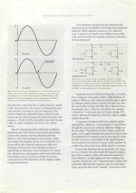
I was a little quick in saying the bias needs to be greater than the peak to peak swing. Actually all we can say is that the bias must be sufficiently high so that the force is always great enough to keep the plates against the bumps stops, if they exist. If the bias were just equal to the AC amplitude (1/2 the peak to peak) then the force goes from 0 to 4 times the no bias levels, as shown in my figure. Assuming the bias is + then we need to have Vmin = DC - AC amplitude is sufficiently large so that sufficient charge is maintained in the cap to keep the plates on the bump stops. I don't have any idea what this would be and it will likely be a function of the cap and its structure. But there is one thing for sure. If the dielectric were to behave as a linear spring I think a DC bias can only hurt. Aside from the fact that in such a case the variation in C would follow the force, which as I showed is highly asymmetric, even in the case of a symmetric force, if the spring is elastic then the change in dielectric thickness would be independent of the DC bias. We could write the spacing as d0 + d' where d' is the change in spacing. and d0 is the spacing for a given bias. Now since C is proportional to 1/(d0 + d') we see that as d0 gets smaller due to the application of a bias, then, since d' is constant while the capacitance is larger for a given bias since d0 is smaller) the change in capacitance is larger.
Now another point is that if the plates were against bump stops d would not vary at all so all distortion from forces changing d should go to zero. I.E., the application of a bias should driver the cap toward linear. If even order distortion is introduced the system is becoming more nonlinear because of asymmetries in the variation of d. So if even order distortion appears we can conclude that we have not pined the plates against the bump stops. Thus it become a question of what is the total distortion. and how does it behave as a function of bias. I don't think that, if dielectric thinning is the mechanism, a conclusion can be made that DC bias of any magnitude will decrease distortion. It may trade off odd order for even order but, and this may be a function of bias. I'll look at the paper and get back on this.
As for cap being transducers, that statement applies to cap, inductors, transistors, vacuum tubes, etc. put a resistor across a tube amp and power it up. With many tube amps I've owned it's easy to hear the tubes singing. Same with several transistor amps I've used. Were all familiar with transformer hum. The bottom line is that any time an AC signal is applied to a device we have oscillation charge which means oscillating forces which means mechanical vibrations. I guess all of these are potentially capable of generating distortion, no?
I took a brief look at the paper. I don't see anythign basically wrong with what he has done. I'd have to work through the details to be sure. He does assumes that the dielectric is a linear spring. However, he shows no evidence that a DC bias reduces distortion. That is just a stament made in the discussion section with no supporting evidence at all. This seems odd since all he would have had to do to show this is do some simulations with Vct including a Dc component. I certainly would not make such a statment without supporting data.
[edit]
I don't think it is necessary to actually solve the circuit equation here. I think it should sufice to solve for the variation of d for a sine wave voltage across the cap. Then look at the behavior of C(t). Since all nonlinear distortion in the voltage across a load connected to the cap would ne a result of nonlinearities in C(t), C(t) is all we need to look at.
Hello John
'However, he shows no evidence that a DC bias reduces distortion. '
From what I have read it actually increases distortion levels slightly.
Rob🙂
'However, he shows no evidence that a DC bias reduces distortion. '
From what I have read it actually increases distortion levels slightly.
Rob🙂
I just realized that my previous post was ambiguous. What I meant was that there have been speakers made where the transducer is a capacitor that deliberately uses electrostriction to create sound, similar to a piezoelectric transducer - the opposite of what you're trying to do here.
Mr Evil said:I just realized that my previous post was ambiguous. What I meant was that there have been speakers made where the transducer is a capacitor that deliberately uses electrostriction to create sound, similar to a piezoelectric transducer - the opposite of what you're trying to do here.
There are lots of them. Called ESL. 🙂
Indeed, but I mean ones that are solid and produce sound by the dielectric actually changing thickness, compared to an ESL where sound is created by a diaphragm of fixed thickness moved through the air.john k... said:
There are lots of them. Called ESL. 🙂
what is the ideal amount of positive biased curent
and why is there no diode to help prevent voltage being pushed back into the battery or using two diode with different resistors for different electron flow rates for each polarity to have a dampening effect and more precise electron flow in the other direction
and why is there no diode to help prevent voltage being pushed back into the battery or using two diode with different resistors for different electron flow rates for each polarity to have a dampening effect and more precise electron flow in the other direction
"and why is there no diode to help prevent voltage"
Why would you need a diode?? You have a 2 meg path and a 8 ohm path. Where is the current going to flow?? You have a short and an open. You also have an RC time constant so the DC should be stable.
Rob 🙂
Why would you need a diode?? You have a 2 meg path and a 8 ohm path. Where is the current going to flow?? You have a short and an open. You also have an RC time constant so the DC should be stable.
Rob 🙂
OK I had some time and worked up some code to solve for the variation in dielectric thickness for a give applied voltage using Menno's equation. I looked at the result below the cap resonance frequency. This is like looking at a driver in the compliance controlled region. Above resonance I don't think there is a problem because the cap plates will not be able to follow the applied signal.
Anyway, what I found, and it will be case dependent, is that w/o a DC bias the THD is all odd order just as I expected. When a DC bias is applied the results are strongly bias level dependent. If the DC bias is of the same amplitude as the applied AC signal then what I see is the introduction of even order distortion in addition to the odd order. There is very little reduction in the odd order distortion so basically the DC bias just adds even order harmonics. Example 3rd order when from .248% to .237%. If you plot the unbiased result and draw a line through the data points, when biased as noted the even order data falls pretty much on the same line.
If I increase the DC bias to the peak to peak voltage what I see is higher even order with very little reduction in odd order. 3rd goes form 0.248 to 0.203
Raising the DC Bias to twice the peak to peak AC level increases the even order further and there starts to be a reduction in 3rd order to 0.1%. But at this point 2nd order HD is up over 3%.
Now, I wouldn't place too much faith on the numbers but the trends are what is of interest. This really says that if the dielectric is a linear spring then this isn't a disortion reducing mechanism. In fact it is sort of a dynamic distortion generator. If the signal level is low compared to the bias (soft passage of music) then you might expect high even order HD on top of the odd order. As the passage gets louder the even order Hd will become lower in amplitude with odd order rising.
Frankly I don't think the analysis is sufficient. It should be pretty obvious that the dielectric can only be compressed so much. I think it needs to be considered as a nonlinear spring.
Sonus Faber use a shunt inductor (with resistive attenuation) to achieve their capacitorless high pass filter. Seems to be a nice elegant solution.
By doing that, you substitute electrostriction for magnetostriction (the effect that causes annoying transformer buzzing). It might be better, or it might not.David Gatti said:Sonus Faber use a shunt inductor (with resistive attenuation) to achieve their capacitorless high pass filter. Seems to be a nice elegant solution.
Of course all this nonsense is why I only make active crossovers now, if I have a choice. Trying to put high voltages and currents through reactive components is just asking for nonlinearity.
Mr Evil said:
By doing that, you substitute electrostriction for magnetostriction (the effect that causes annoying transformer buzzing). It might be better, or it might not.
Of course all this nonsense is why I only make active crossovers now, if I have a choice. Trying to put high voltages and currents through reactive components is just asking for nonlinearity.
I've measured distortion in a lot of caps and inductors and frankly never seen it to be a problem. Tht is one of the reasons this article and thread are on interest to me.
Looks like JBL Altec/Lansing did this way back in 1993, and judging by the forum discussions, it didn't work then and it won't work now.
http://www.hostboard.com/forums/altec-users-board/187625-capacitor-biasing-crossovers.html
Here is another link to the Altec K2 xovers
http://manuals.harman.com/JBL/HOM/Technical Sheet/K2S9800-9800SE ts.pdf
Cheers George
http://www.hostboard.com/forums/altec-users-board/187625-capacitor-biasing-crossovers.html
Here is another link to the Altec K2 xovers
http://manuals.harman.com/JBL/HOM/Technical Sheet/K2S9800-9800SE ts.pdf
Cheers George
Attachments
- Home
- Loudspeakers
- Multi-Way
- DC Bias in Crossovers (mostly Tweeters)