Perry I found the shorted ic it was a 2068 dual op amp , now all the ic have 7-8 volts +/-. I was tring to find a short or open resistor or transistor but no go yet ? What would be the best way to test them ohms with no power or power on and volts test ?
What problem was the 2068 causing?
I don't understand the question. What are you trying to measure the resistance on?
I don't understand the question. What are you trying to measure the resistance on?
Perry the 2068 was shorted all pins , all output regulators ic voltage was 2+/- volts after removing this ic 2068 voltage on all ic went to 7-8 +/- volts . Now I have waveforms as should on ic's. Iam sorry about that ,what is the best way to mesure the output drive tranistors ?
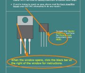
The best way to check them is out of the circuit. If you're unsure of the readings you get, use the applet on this page.
Basic Amplifier Repair - Transistor Test Applet Link
Basic Amplifier Repair - Transistor Test Applet Link
Attachments
Its been a while but Iam back . Ok replaced 2068 . Now when I power up the amp relay turns on I have 10 volts on output terminals and move a driver board it goes back to 0.00 volts ? Bad ic transistor or bad solder connection ? Everything looks good solder joins . But after voltage goes away from speaker terminals . I input a sine wave 1000hz good wave form, good signal sine wave on first 2 2068s but after that other 2068s have no wave form , all op amps have +12 / -12. And with 0.00 on output terminals I get no signal wave form , but when I connect a speaker to outputs it jumps to 20volts on ouputs ?
It's difficult to say what's causing the intermittent connection. If you had to desolder the driver board, some of the vias may be damaged. If that's so, you may have to solder from the top of the board also.
1k is probably too high. Try 100Hz.
1k is probably too high. Try 100Hz.
Ok Perry sounds good, it looks to be fun lol . Ok 100hz Ill set it up , its a function generator is that ok to use for signal to the input for the rca's ? Thank you.
Ok Im back , life just got in the way . Back to my passion. Fixed the problem with output driver boards soldered from top too. I have one with a quick disconnect so I can make probing much ezer. Now output fets burn up quick, lm361 does not look good either no triangle wave form on pin 4 and on 9 and 11 do not have square wave form. These are soldered very good to main board . I have both +12 and - 12 volts on ic's and +60 and -60 rail voltage . Thank you in advance Perry.
Without the triangle waveform on pin 4, you won't have a square wave output. Post the DC voltage on all pins of the LM361.
IC#
Pin 1:
Pin 2:
Pin 3:
Pin 4:
Pin 5:
Pin 6:
Pin 7:
Pin 8:
Pin 9:
Pin 10:
Pin 11:
Pin 12:
Pin 13:
Pin 14:
IC#
Pin 1:
Pin 2:
Pin 3:
Pin 4:
Pin 5:
Pin 6:
Pin 7:
Pin 8:
Pin 9:
Pin 10:
Pin 11:
Pin 12:
Pin 13:
Pin 14:
Ok heres's what I got on the LM361
IC#
Pin 1: 11.87
Pin 2: 0.00
Pin 3: 4.79
Pin 4: 1.70
Pin 5: 0.00
Pin 6: -12.38
Pin 7: 0.00
Pin 8: 2.90
Pin 9: -1.70
Pin 10: -1.80
Pin 11: 2.70
Pin 12: 0.00
Pin 13: 2.90
Pin 14: 2.90
IC#
Pin 1: 11.87
Pin 2: 0.00
Pin 3: 4.79
Pin 4: 1.70
Pin 5: 0.00
Pin 6: -12.38
Pin 7: 0.00
Pin 8: 2.90
Pin 9: -1.70
Pin 10: -1.80
Pin 11: 2.70
Pin 12: 0.00
Pin 13: 2.90
Pin 14: 2.90
Are the output transistors in the board right now?
Post the DC voltage on all 8 pins of the TL072 on the board with the LM361.
IC#
Pin 1:
Pin 2:
Pin 3:
Pin 4:
Pin 5:
Pin 6:
Pin 7:
Pin 8:
Post the DC voltage on all 8 pins of the TL072 on the board with the LM361.
IC#
Pin 1:
Pin 2:
Pin 3:
Pin 4:
Pin 5:
Pin 6:
Pin 7:
Pin 8:
No Iam sorry I forgot to tell you that , no output transistor in output.
IC# TL072
Pin 1: .70
Pin 2: .10
Pin 3: 0.00
Pin 4: -12.00
Pin 5: 0.00
Pin 6: 0.00
Pin 7: 0.00
Pin 8: 11.90
IC# TL072
Pin 1: .70
Pin 2: .10
Pin 3: 0.00
Pin 4: -12.00
Pin 5: 0.00
Pin 6: 0.00
Pin 7: 0.00
Pin 8: 11.90
- Status
- Not open for further replies.
- Home
- General Interest
- Car Audio
- DB Drive 1200